Operation
Turning extraction unit On
The main isolation switch must be switched to the “On”
position (Refer to section
1
for switch location) by
depressing the ‘I’ side of the switch.
Setting the desired airflow
The V600 features manual flow control. This enables the
user to set the required airflow rate. Over time as the filters
begin to block the user should manually increase the motor
speed to ensure the correct flow is maintained to
compensate for any loss in performance caused by the
added restriction of the partially blocked filters.
The extractor and all pipe work must be fully
installed and connected before the airflow is set.
To set the airflow
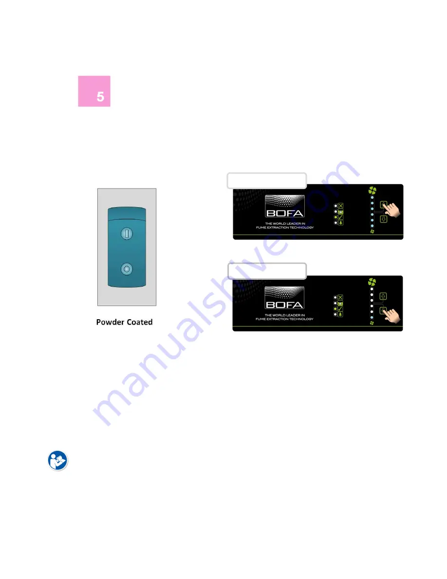
Press the Up arrow button to increase airflow and press the
down arrow button to decrease airflow. The level of airflow
is indicated by the vertical row of six blue LEDs to the right
of the mains isolation switch. As the airflow increases, more
blue LEDs light up and the opposite for decreasing the
airflow.
Remote Speed Control
If your V600 extraction unit is installed with this optional
extra the airflow can be remotely controlled from a
controller run from the unit on a signal cable. The airflow is
adjusted in the same way as detailed above.
01
Increase Airflow
Decrease Airflow
Summary of Contents for V600
Page 1: ...V600 Issue 2 Jan 2017 ...
Page 2: ......


