14
www.bodine-electric.com
Manual Speed Control
A Manual Speed Potentiometer Kit for
controlling motor speed is supplied
with the Model ABL- 3911C and ABL-
3921C . The kit contains a 10K Ohm
potentiometer, mounting hardware, and
three 24-inch long leads terminated on
one end with 1/4 inch quick connects .
To connect the speed potentiometer,
proceed as follows:
1 . Solder the three leads to the
potentiometer as shown in Figure 1 .
2 . Mount the potentiometer in the
desired location .
3 . Connect the speed pot to the control board terminals as follows:
• Blue to Terminal “S1”
• Orange to Terminal “S2”
• Yellow to Terminal “S3”
Manual Braking (Disable), Direction
of Rotation, and Deceleration
Mechanical switches or relays
can be used to switch the control
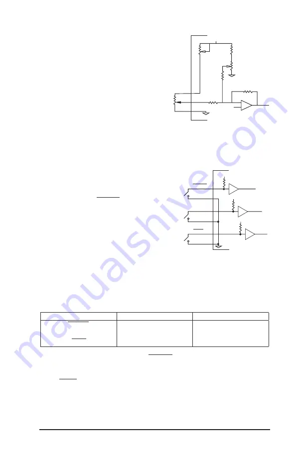
inputs . Figure 8 shows a schematic
representation of manual or relay
switched inputs .
NOTE: Shielded cable is recommended for the these
connections .
The following chart lists the control functions relative to the state of the
mechanical switches or relays
.
Switch
Closed
Open
DISABLE
1
Stop
Run
DIR
2
CW
4
CCW
4
DECEL
3
Decelerate
Accelerate
1 . Dynamic braking will occur when the DISABLE switch is closed .
2 . A”Smart Reverse Circuit” prevents plug reversing when the DIRection switch is
opened or closed . The motor brakes to a stop before changing direction .
3 . The DECEL switch controls soft stops . The degree of deceleration can be varied
with the trim potentiometers on the control board . See Page 20 .
4 . The output shafts of gearmotors with odd number of stages (Bodine type
designations ending with WX, E1, or E3) will rotate in the opposite direction .
15
3. Connect the speed pot to the control board terminals as follows:
• Blue to Terminal "S1"
• Orange to Terminal "S2"
• Yellow to Terminal "S3"
Manual Braking (Disable), Direction
of Rotation, and Deceleration:
Mechanical switches or relays can be
used to switch the control inputs.
Figure 7 shows a schematic representa-
tion of manual or relay switched
inputs.
NOTE: Shielded cable is recommended
for the these connections.
The following chart lists the control
functions relative to the state of the
mechanical switches or relays.
Switch
Closed
Open
DISABLE
1
Fast Stop
Run
DIR
2
CW
4
CCW
4
DECEL
3
Slow Stop
Run
1. Dynamic braking will occur when the DISABLE switch is closed
2. A"Smart Reverse Circuit" prevents plug reversing when the DIRection switch is opened or
closed. The motor brakes to a stop before changing direction.
3. The DECEL switch controls soft stops. The degree of deceleration can be varied with the trim
potentiometers on the control board. See Page 21.
4. The output shafts of gearmotors with odd number of stages (Bodine type designations ending
with W3, E1, or E3) will rotate in the opposite direction.
Figure 7 - Manual Switch and
Relay Control Inputs.
Manual
Switches
or Relay
Contacts
12V
10K
4000 Series
CMOS
12V
10K
12V
10K
4000 Series
CMOS
4000 Series
CMOS
DISABLE
DISCOM
DIR
DIRCOM
DECEL
DECLCOM
Signal Common
Figure 8 – Manual Switch and
Relay Control Inputs.
14
Fuse Installation:
The control input and output are fused. The line input fuse
has been installed at the factory. The control output or "Motor Fuse" must be
selected based on the size of the motor.
Line Fuse:
The location of line fuse (F1) is shown in Figure 4. It should
always be replaced with a fuse of the same type and rating. Its rating can be
determined by referring to the chart in Figure 5.
Motor Fuse:
The location of motor fuse (F2) is shown in Figure 4. The fuse rating
will vary with the size of the motor used. To determine the proper fuse rating,
locate the first four digits of your motor's type number on the motor nameplate.
Find the same four digits in the chart in Figure 5 to determine the fuse size. The
ABL-3911C and ABL-3921C are supplied with the fuses listed in Figure 5.
Manual Control Input Connections:
Motor speed, braking, direction of
rotation and deceleration can be controlled manually or electronically. Refer to
the following procedures for connecting control inputs.
CAUTION
The control board signal common is not at ground potential. Any
external signal or equipment connected to the control must be
electrically isolated from ground (e.g., with relay contacts or
optical isolation module). Non-isolated signals will damage the
control and/or associated external equipment.
Manual Speed Control:
A Manual Speed
Potentiometer Kit for controlling motor
speed is supplied with the Model ABL-
3911C and ABL-3921C. The kit contains
a 10K Ohm potentiometer, mounting
hardware, and three 24-inch long leads
terminated on one end with 1/4 inch quick
connects. To connect the speed potenti-
ometer, proceed as follows:
1. Solder the three leads to the potenti-
ometer as shown in Figure 1.
2. Mount the potentiometer in the
desired location.
12V
10K
10K
100K
10K
100K
S3
S2
S1
51.1K
Signal Common
Signal Common
Maximum
Speed
Adjustment
Minimum
Speed
Adjustment
10K
–
+
Figure 6 - Manual Speed
Potentiometer/Interface details.
Figure 7 - Manual Speed
Potentiometer/Interface details.


