T.O. BMS1F-16CM-1
BMS 4.34 Change 2.00
BMS 4.34 Dash 1
© Red Dog 2012-2019
Page: 148
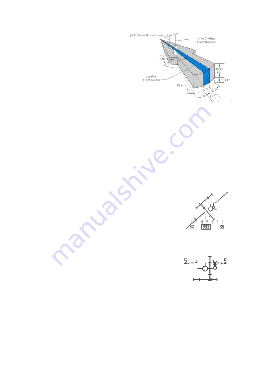
The coverage zone for the localizer mirrors the
USAF instrument manual description (AFMAN
11-217 VOL 1). There's a relatively narrow
18Nm radius pie wedge shaped coverage zone
centred on the extended runway centreline.
There is a second fatter pie wedge of radius
10Nm similarly centred. Middle and inner
markers are also positioned at specific distances
from the runway threshold, unless their
placement is not possible for topographic
reasons (approach track over water for instance
as it is the case for both Kunsan runways).
ATC vectoring procedures in real life are
designed to get you roughly in the
neighbourhood of the localizer at or around 2000' AGL (given roughly flat terrain in the vicinity of the
base). From there you are vectored into the coverage zones as appropriate. Now, if you have the
CMD STRG mode-selected in the DED page when you cross into the coverage zone, a CMD STRG
cue pops up. This is a plain small circle that is tied to the HUD horizon line. It moves back and forth
across that line to guide you to a 45 degree intercept of the extended runway centreline that the
localizer transmits along.
The cue is fixed to the horizon line because the idea is that you fly level at 2000' to intercept the
localizer first and then the glideslope (GS) from below, usually around 6-7 Nm from the runway
threshold. The GS cues will remain invalid till you are close enough to its centre (5° = 2 dots). As long
as that is the case the command steering cue will not display the top thick mark and the GS bar will
most likely stay dashed (HUD) on top of the instrument (ADI).
So you are flying along on the 45° intercept heading and start to get within 5 degrees (=2 dots) of the
localizer centreline. At this point the localizer deviation bar (HUD, ADI and HSI) should start to come
alive and the CMD STRG cue will start to swing you onto the approach course.
As you continue inbound you'll get to within 2-3 degrees of the glide slope.
When you do, the GS deviation bar will start to descend. Depending on
exactly where you are in the approach course, around this time or shortly
thereafter you will be close enough to the GS centreline to get pitch steering.
The CMD STRG cue will unglue from the horizon line and will grow a fat
‘tick’
on top of it (the tick mark means that pitch steering cues are provided).
The main thing now is to let the GS descend to the centre. When the glide
slope is centred, you are declared on glide on loc and
it’s usually at the moment you overfly the outer
marker. It’s time to lower the gear. That will provide a slight pitch down movement that will be just
enough to lower the FPM to the -2.5° dashed line and keep the glide slope centred. Maintain the CMD
STRG aligned with the FPM, the cross perfectly centred and lower your
airspeed to on speed AOA using the AOA bracket.
One other thing about the CMD STRG cue: if you start to drift above the GS
centreline after you have intercepted it and drift to the point that you risk
losing pitch steering the fat tick will have an "X" superimposed over it. This
is your cue to pull back on power and/or drop the nose as appropriate.
The CRS setting can be set to the runway approach course in the T-ILS page. Normally the CRS
setting must be correctly aligned for the CMD STRG cues to work correctly, but that is not yet valid in
BMS. The CRS setting in the DED is totally separate from the one on the HSI. There is no relationship
whatsoever in the avionics suite (i
t’s not the case when the aircraft is equipped with the EHSI). It is
advised to set both according to runway approach course, but apart from the risk of confusion when
they are not set correctly it has no consequences in BMS.
With the HUD in ILS mode a V is placed on the HUD heading tape according to current winds. This
cue gives you the wind corrected heading you need to steer to maintain the desired approach course.
Summary of Contents for F-16C/D 4.34
Page 30: ...T O BMS1F 16CM 1 BMS 4 34 Change 2 00 BMS 4 34 Dash 1 Red Dog 2012 2019 Page 30 ...
Page 56: ...T O BMS1F 16CM 1 BMS 4 34 Change 2 00 BMS 4 34 Dash 1 Red Dog 2012 2019 Page 56 ...
Page 121: ...T O BMS1F 16CM 1 BMS 4 34 Change 2 00 BMS 4 34 Dash 1 Red Dog 2012 2019 Page 121 ...
Page 134: ...T O BMS1F 16CM 1 BMS 4 34 Change 2 00 BMS 4 34 Dash 1 Red Dog 2012 2019 Page 134 ...
Page 176: ...T O BMS1F 16CM 1 BMS 4 34 Change 2 00 BMS 4 34 Dash 1 Red Dog 2012 2019 Page 176 ...


