BVC6200LM Instruction Manual v.01
- 9 -
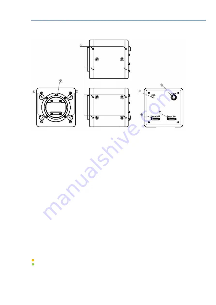
3. Parts allocation and functions
3.1 Parts allocation
①
Lens mount
:
Use M52 mount Lens
The following are available by BlueVision
BV-L1020-M 20mm F2.8
BV-L1024-M 24mm F2.8
BV-L1028-M 28mm F2.8
BV-L1035-M 35mm F2.8
BV-L1050-M 50mm F2.8
BV-L1105-M 105mm F2.8
② LED:
For power ON/OFF, Trigger input
③ 12P connector:
Input DC 12V to 24V
(Refer to sections 4.3 and 4.4 for the pin assignment)
④
Camera Link connector
:
Mini camera link connector for image output and trigger input
(Refer to sections 4.1 and 4.2 for the details)
⑤
Holes for camera
There are the set of four holes on the front, top and bottom for
setting screws fixing screws of camera. It is M4 6mm depth. Four holes on the
top/bottom will be used for optional tripod base, BVA-TB01.
3.2
LED indication
Orange lighting: Initialize the camera
Green lighting
:
In operation
✹
Green flashing
:
Receiving an external trigger
Top
Front
Bottom
Rear


