background image


Setup 

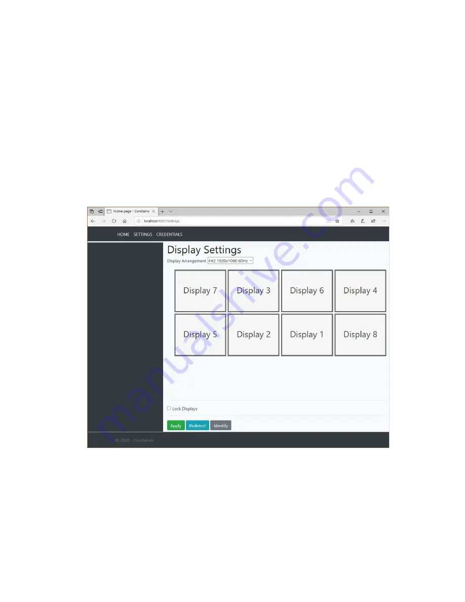
Display Settings: 
 
The remote display settings page allows the user to arrange the display layout on the video wall 
appliance. 
 
The “Display Arrangement” drop-down contains the current available arrangements based on the 
connected and discovered outputs in addition to what resolutions the displays attached support.


Once the desired layout/mode has been selected the display grid arrangement will update to show 
the current monitor arrangement. 
 
Pressing “Identify” will display the output ID(s) on the monitor(s). Use the grid to drag displays to the 
desired desktop position without physically unplugging and plugging video cables.


Once layout is correct use the “Apply” button to update the settings on the video wall appliance.


If any displays are not detected it is recommended to press the “Redetect” button. 
 
Select the “Lock Displays” option to allow monitors to be turned off and on without Windows 
re-arranging the Desktop.


Video Wall Controller Series User Manual

Page 

20 

Copyright © 2020


Summary of Contents for BB-VW-6UHD

Page 1: ...eries BB VW User Manual Contact BlueBox Video Ltd Pontefract Road Unit 5 Courtyard 31 Normanton WF6 1JU United Kingdom Tel 44 7307 052693 www bluebox video Version 31 03 2020 Video Wall Controller Ser...

Page 2: ...d do not accept liability for any errors or omissions BlueBox Video Limited reserves the right to change specification without prior notice it does not represent commitment from BlueBox Video Limited...

Page 3: ...frequency energy and if not installed and used in accordance with the instructions may cause harmful interference to radio communications Operation of this equipment in a residential area domestic env...

Page 4: ...ontents Warranty and RMA Safety Precautions Product Introduction Hardware Specifications Know Your Appliance Getting Started Installation and Setup Video Wall Controller Series User Manual Page 4 Copy...

Page 5: ...of Warranty We always recommend shipping the product using the original packaging As it arrived to you If the returned item s fault is diagnosed to be from user error or mistreatment repairs will be...

Page 6: ...d near the equipment and must be easily accessible 6 Put this equipment on a stable surface during installation Dropping it or letting it fall may cause damage 7 The openings on the enclosure are for...

Page 7: ...unit is always recommended to be installed in a rack cabinet with a supporting rails below if possible The unit should be secured to the cabinet using the 2 mounting tabs 17 Ensure the unit is install...

Page 8: ...t be connected to an earthed outlet socket Note When unpacking inspect the shipment box and appliance to identify any possible damages due to shipping Make sure all items have been delivered and that...

Page 9: ...n action the latest graphics technologies to provide an unrestricted video layout design under a familiar Windows platform An appliance is optionally supplied with the latest Windows 10 operating syst...

Page 10: ...1 2 outputs 1 x AC power inlet Storage Up to 2 x SATA 2 5 HDD SDD for RAID Configuration Up to 2 x SATA 2 5 HDD SDD for RAID Configuration Up to 2 x SATA 2 5 HDD SDD for RAID Configuration Dimensions...

Page 11: ...3 0 Ports Used to connect USB 3 0 2 0 devices Rear Panel AC Power Socket 90V 240V AC Input Plug an AC power cord here before turning on the system USB 2 0 Ports Used to connect USB 2 0 devices GbE LA...

Page 12: ...e unit Make sure that there is ample clearance around the appliance to provide sufficient air flow Power IMPORTANT A common IEC C13 cable is required to power the appliance this is not provided and th...

Page 13: ...ng must be kept clear of any obstruction at all times NOTE Failure to do so will result in the system over heating and potentially damaging your equipment and will invalidate the warranty Liquids hot...

Page 14: ...to allow an unrestricted flow of air through the unit It is recommended to periodically power down unit and disconnect from wall outlet and remove any built up dust from the side ventilation holes an...

Page 15: ...onnect required graphics outputs starting from left to right looking at the rear of the unit to the monitor s Looking at the rear panel the Outputs run from left to right 1 to N Connect graphics outpu...

Page 16: ...se the Windows Run command and type netplwiz Follow the instructions presented When you change the user account Password ensure that you update the details found in netplwiz for the automatic login fe...

Page 17: ...ance Network Settings Add Video Network Sources i e NVR VMS server credential settings Update appliance Firmware Restart and Shutdown Appliance The appliance will show the AWP IP Address on the units...

Page 18: ...Setup Dashboard Displays appliance key system metrics such as CPU Usage and Temperatures Video Wall Controller Series User Manual Page 18 Copyright 2020...

Page 19: ...gs Allows user to configure network port settings including static and DHCP settings Global Settings General hardware and software settings Upload Firmware Allows a new software release to be uploaded...

Page 20: ...t will update to show the current monitor arrangement Pressing Identify will display the output ID s on the monitor s Use the grid to drag displays to the desired desktop position without physically u...

Page 21: ...e and display the current settings for each Pressing the Edit button for each of the ports will open a dialogue window which allows the user to change the current settings This includes both IP and DN...

Page 22: ...t number of the NVR VMS Username username of NVR VMS Password password of NVR VMS Video Cache Playout buffer length in milliseconds default is 500 Prefer UDP over TCP Stream using a UDP connection def...

Page 23: ...is accessible on the same network as the NVR VMS server Contact your support operative Using the NVR VMS client provided software drag video inputs from the toolbar onto any of the appliance screens...

Reviews: