Blue-White FLEXFLO A2 Series Operating Manual Download Page 31

13.0   TFD (Tube Failure Detection)

Flex-Pro is equipped with a 

Tube Failure Detection 

System which is designed to 

stop pump and provide an output alarm in event pump tube should rupture and 
chemical enters pump head. Pump will detect a chemical with a conductivity 
reading greater than 500 microsiemens. Chemicals with a conductivity of less 
than 500 microsiemens will not be detected.

This patented system is capable of detecting presence of a large number of 
chemicals including Sodium Hypochlorite (Chlorine),  Hydrochloric (muriatic) 
Acid, Sodium Hydroxide, and many others. System will not be triggered by water 
(rain, condensation, etc.) or silicone oil (roller and tubing lubricant).

Chemical from tube failure

Flex-Pro has a built in Pump Tube Timer. Timer starts when rotor is rotating and stops when rotor is idle.

To view current Pump Tube Timer value, press and hold START button, then press and release DOWN arrow.

Tube Timer screen will appear. Screen will display current Pump Tube Time in run-time hours. Tube Timer screen 
will display for 4 seconds and then switch back to previous operating display screen.

While displayed, press START button twice to reset Pump Tube Timer to zero.

When replacing pump tube, pump will ask you if you’d like to reset Pump Tube Timer. If you choose YES, screen 
will display current Pump Tube Time for 5 seconds before timer is reset to zero.

If system has detected chemical, pump tube must be replaced and pump head and roller assembly must be 
thoroughly cleaned.  Failure to clean roller assembly will void warranty.

If TFD alarm occurs, pump will stop, close an alarm output, and screen will flash TFD with an alarm icon.

Confirm Chemical Detection

To determine if your chemical will be detected by system, remove pump head cover and pump tube and roller 
assembly.

Place a small amount of chemical in bottom of pump head - just enough to cover sensors. Replace pump head 
cover only.

Turn on pump (press START). If TFD system detects chemical, pump will stop after a two second confirmation 
period and TFD Alarm screen will display. If TFD system does not detect chemical, pump will continue to run after 
confirmation period.

Carefully clean chemical out of pump head being sure to remove all traces of chemical from sensor probes. 
Replace roller assembly and tubing. Replace pump head cover. Press START button to clear alarm condition and 
restart pump.

12.0  Pump Tube Timer

Tube Life Timer

Display tube life timer.
Press and hold START button.
Press and release DOWN arrow.

Displays amount of total runtime hours on currently installed tube.
Time will be displayed in hours.
Timer will be display for approximately 4 seconds before returning to 
previous runtime screen.

236

1

SPEED

Hours

Page 31

Page 30

®

FLEXFLO  A2

®

FLEXFLO  A2

Pump has a built in 3 amp alarm output relay. Relay is pre-configured to energize on tube failure detection (TFD) 
and on Flow Verification Sensor (FVS). 

A Flow Verification Sensor must be installed and configured for relay to trigger on no-flow conditions.

Prior to service, pump clean water through pump and suction / discharge line to remove 
chemical.

Always wear protective clothing, face shield, safety glasses and gloves when working on or 
near your metering pump.  Additional precautions should be taken depending on solution 
being pumped. Refer to MSDS precautions from your solution supplier.

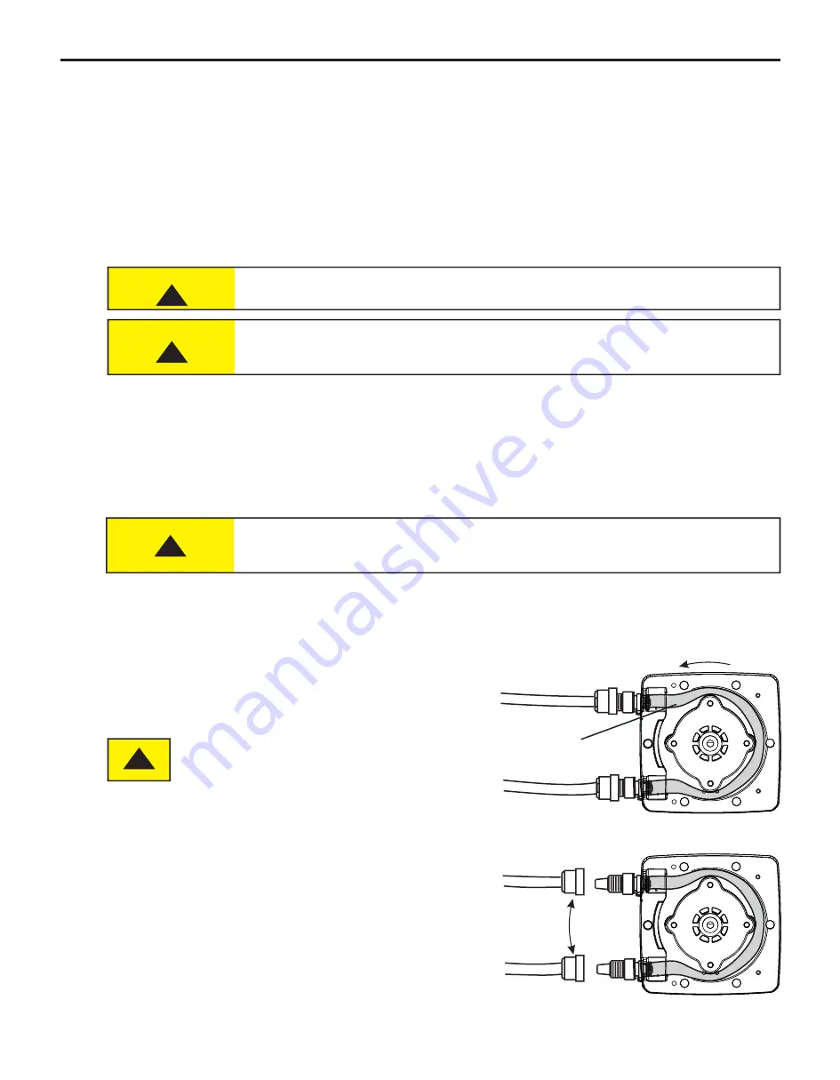
Reverse rotation of pump; press and hold REVERSE ROTATION button until rotor begins rotating in opposite 
direction. This process can be used for many reasons throughout various industries.

Two reasons for reversing current rotor rotation; to purge chemical from tubing and to extend tube life.

Plan ahead before reversing rotor rotation. If check valves are installed, make necessary arrangements to allow 
back flow.

If your desire is to simply extend tube life:

Typically tubing fails on outlet side (pressure side) of tube assembly in pump head.  

Failure to install check valves in their proper flow direction can cause excess pressure 
(PSIg) build up in system and can result in tube rupture.
Always use extreme caution and ensure proper connections when using this feature. 

Swap Inlet

and Outlet

ON

R

T

F

Reversing rotation, moves outlet side (pressure side) to 
opposite side of tube assembly, greatly increasing tube life.

Stop pump before tube failure occurs.

Disconnect power from pump. Carefully purge any pressure 
in discharge line of pump. Disconnect suction end tubing and 
discharge end tubing from pump head tubing.

IMPORTANT! Swap sides of suction (inlet) and discharge 
(outlet) tubing. No need to remove Pump Head Cover.

Double check all connections before starting pump.

ON

R

T

F

Outlet

Inlet


D

ir

n

e

o

i

c

t

t

a

i

t

o

o

n

R

Typical Failure Point

(pressure side)

!

CAUTION

!

CAUTION

!

CAUTION

!

15.0  Reverse Rotor Rotation

14.0  Alarm Relay

Summary of Contents for FLEXFLO A2 Series

Page 1: ...Peristaltic Metering Pump Series A2 FLEXFLO...

Page 2: ...7 7 2 Mode 0 Set FVS flow verification system 18 7 3 Mode 0 Set 4 20mA Output 20 8 0 Mode 1 Manual Operation 22 8 1 Mode 1 Manual Operation Screen Shots 23 9 0 Mode 2 4 20mA Input Operation A2V PUMP O...

Page 3: ...Page 3 FLEXFLO A2 READ THE INSTRUCTION MANUAL PRIOR TO INSTALLATION AND USE 1 714 893 8529 sales blue white com customerservice blue white com 5300 Business Drive Huntington Beach CA 92649...

Page 4: ...You may notice trace amounts of clean water in pre installed tube assembly This is part of our stringent quality assurance program at Blue White Industries 1 1 Available Models n Raise metering pump...

Page 5: ...z 1ph 1 0 Amp Maximum Power Cord Options 115V60Hz NEMA 5 15 USA 230V60Hz NEMA 6 15 USA 220V50Hz CEE 7 VII EU 240V50Hz AS 3112 Australia New Zealand 230V50Hz BS 1363 A UK Motor Brushed DC 1 8 H P Duty...

Page 6: ...onents Pump Tube Assembly Tubing Flex A Prene Flex A Chem or Flex A Thane Adapter Fittings PVDF Injection Back Flow Check Valve Body Insert PVDF Check Ball Ceramic Spring Hastelloy C 276 Ball Seat O R...

Page 7: ...Compatible with Blue White s output Flow Verification Sensor FVS system Enclosure Rating NEMA 4X Constructed for either indoor or outdoor use to provide a degree of protection to personnel against inc...

Page 8: ...sure Keep discharge pressure as low as possible to maximize tube life 4 2 Dimensions All diagrams are strictly for guideline purposes only Always consult an expert before installing metering pump on s...

Page 9: ...ner for 1 3cm I D Connection End Models Suction Tubing and Strainer Weight Ceramic Suction Tubing PVC 3 8 95 cm OD X 1 4 64 cm ID Strainer Polypropylene PVDF PVDF O Ring TFE P optional EP O Ring TFE P...

Page 10: ...has an auto restart feature which will restore pump to operating state it was in when power was lost Note When in doubt regarding your electrical installation contact a licensed electrician Electrica...

Page 11: ...GATIVE SIGNAL T7 RELAY OUT 1 2 3 N C COM N O INPUT POWER T11 1 T11 T11 2 3 T11 GROUND NEUTRAL COMMON LINE HOT 1 2 3 POWER AC VOLTAGE 115V OR 230V AC MANUAL SWITCH 50 60 HZ 100W GROUND NEUTRAL LINE HOT...

Page 12: ...3 N C COM N O T1 1 3 PLS 4 4 20 2 Motor Active 5 GND T1 T1 2 3 CLOSED WHILE MOTOR IS ENERGIZED NEGATIVE SIGNAL OUT 4 7K OHM MOTOR ACTIVE 5 TO 24 VDC INPUT POWER T11 1 T11 T11 2 3 T11 GROUND NEUTRAL C...

Page 13: ...al if enabled Press and release To Stop pump Press and release Press DOWN arrow to decrease pump speed output in Manual Operation To decrease value while in programming mode To view amount of run time...

Page 14: ...w to increase pump speed output in Manual mode Mode 1 Press and release To Start pump To begin listening reacting to external signals Press and release To Stop pump Press and release To scroll through...

Page 15: ...t Mode 2 and press START button to allow pump to be controlled by external 4 20mA signal Mode 3 Frequency Hz Input Signal Run pump remotely via external high frequency Hz signal Press and Hold Select...

Page 16: ...cted previously then YES will be displayed on screen Step 3 Press and release DOWN arrow to change setting to YES To change setting back to NO press and release UP arrow Step 4 After you ve made your...

Page 17: ...ton to clear alarm Step 1 Press and release STOP button Note Mode cannot be changed while pump is in running Press and release SELECT RUN MODE button multiple times until Mode 0 is selected Step 3 Ste...

Page 18: ...screen continue to press and release RIGHT arrow button until FVS icon appears Step 4 FVS icon will appear for 1 second followed by numbers These numbers indicate delay time setting for FVS Select a...

Page 19: ...verification system Continued Sensor Model Number Actual Working Range with Flex Pro Pump ML Min ML Min 30 200 FV 100 30 300 Published Flow Range 50 900 FV 200 100 1000 100 1800 FV 300 200 2000 300 3...

Page 20: ...in running Press and release SELECT RUN MODE button multiple times until Mode 0 is selected Step 2 With Mode 0 selected press and hold SELECT RUN MODE button until Remote icon begins flashing This ind...

Page 21: ...w To decrease value press and release DOWN arrow To save value press and release RIGHT arrow Mode 0 100 0 0 MAOUT 4 20 mA Icon SPEED Step 7 Output signal at maximum speed will now be displayed To incr...

Page 22: ...entered Setup menu Step 4 Pump will now operate at your pre configured speed Press and release START button to start pump Press and release STOP button at anytime to stop pump With pump operating in m...

Page 23: ...see page 16 9 6 mA 1 35 0 1 SPEED OUT Runtime Screen Shot 3 Display motor speed percentage Press and release RIGHT arrow to view percentage of motor speed 35 0 1 SPEED Runtime Screen Shot 4 Display t...

Page 24: ...ing This indicates that you ve entered Setup menu Step 3 Minimum pump speed will be displayed To increase value press and release UP arrow To decrease value press and release DOWN arrow To save value...

Page 25: ...100 4 mA 20 Pump Output 16 mA 43 8 Pump Output 0 Output Pump Motor Speed Pump Motor Speed 100 Output 100 Output 0 Output 43 8 Output 20 Output Milliamp input mA from external source Milliamp input mA...

Page 26: ...le times until Mode 3 is selected Step 2 With Mode 3 selected press and hold SELECT RUN MODE button until Speed icon begins flashing This indicates that you ve entered Setup menu Step 3 Pump speed at...

Page 27: ...d Ultrasonic Flowmeter NEMA 4X IP 66 Industries Ltd ProSeries by Blue White Ind TM Doppler Transit Time Discharge Line Paddlewheel Flow Sensor Meter Ultrasonic Flow Meter Injection Point Example 1 Ult...

Page 28: ...selected press and hold SELECT RUN MODE button until On icon begins flashing This indicates that you ve entered Setup menu Step 3 Pump on time will be displayed in either MIN minutes or SEC seconds T...

Page 29: ...WN arrow To save value press and release RIGHT arrow 1 Mode 4 Mode 4 OFF 4 Hz ON 4 1 0 Hz ON SPEED Hz ON 11 0 Mode 4 Pulse Batch low speed pulse Operation A2V Pump Only Continued Runtime Screen Shot 1...

Page 30: ...mer If you choose YES screen will display current Pump Tube Time for 5 seconds before timer is reset to zero If system has detected chemical pump tube must be replaced and pump head and roller assembl...

Page 31: ...re reversing rotor rotation If check valves are installed make necessary arrangements to allow back flow If your desire is to simply extend tube life Typically tubing fails on outlet side pressure sid...

Page 32: ...o do so will cause solution to squirt when disconnecting tube connections SAFETY FIRST REMOVE PRESSURE Disconnect system plumbing from pump tube adapters Step 2 Press and release STOP button Remove fo...

Page 33: ...tion tool and tubing in direction of rotation Press discharge side of tube adapter securely into pump head Step 4 Press and release STOP button on pump Suction and discharge tube adapter ends should b...

Page 34: ...als Manufacturer does not assume responsibility for damage to pump that has been caused by chemical attack How to Clean and Lubricate Pump Pump will require occasional cleaning Amount will depend on s...

Page 35: ...G MGE MNGG MNEE MG2G Suction lift 3 ft 0 200 400 600 800 1000 1200 1400 0 32 5 65 97 5 130 Motor RPM Flex Pro Model A2 output of water vs motor rpm MND MTH MGG MGE MNGG MNEE MG2G Suction lift 3 ft 0 1...

Page 36: ...lable for Q tubes 7 Quick Disconnect 1 350 17 50 Barb FKM KIT QBV 50 Barb EP KIT QBE 50 M NPT FKM KIT QMV 50 M NPT EP KIT QME 3 8 OD 1 4 ID Tube Compression FKM KIT QSV 3 8 OD 1 4 ID Tube Compression...

Page 37: ...ane 125 ID GG Flex A Thane 187 ID G2G Flex A Thane 187 ID ND Flex A Prene 075 ID NEE Flex A Prene 093 ID NGG Flex A Prene 187 ID TH Flex A Chem 250 ID A2 S GE T Tube Sample Model Number Tube Material...

Page 38: ...the associated product warranty and provides the user with important safety information Purchasers installers and operators of Blue White products should take the time to inform themselves about the...

Page 39: ...and G2G only Q Quick Disconnect Natural PVDF Kynar available for ND NEE NGG and G2G only valves sold seperately MB 1 2 Male BSPT Fitting Natural PVDF Kynar Pump Tube Material Pump Tube Size ND Flex A...

Page 40: ...waste but use the collection framework available to them for the return recycle recovery of WEEE and minimize any potential effects of EEE on the environment and human health due to the presence of h...

Reviews: