Page 30
5.1
Signal Output
Sends a configurable 4 - 20 mA or frequency (Hz) signal to another pump or external device. This feature can be
used to control other pumps (in sync / proportionally), data logging systems, and other external devices for plant
automation.
Default settings:
Disable
Navigate to
Signal Output
menu by pressing MENU button, then selecting Output Setup, and then
Signal
Output
.
Select your desired Signal output using UP or DOWN arrows.
Press ENTER to configure the output signal.
Press UP or DOWN arrow to scroll through 0 - 9 on selected digit.
Press RIGHT arrow to scroll over to the next digit to the right. If you pass your desired digit, you can easily scroll
back by continuously pressing RIGHT button.
Press ENTER to save the changes.
Continue this process until all four screens have been configured.
To navigate back out of the menu structure you must select <-Esc at bottom of every screen menu until you see
Run Mode screen displayed.
Example 1
6
4
8 10 12 14 16 18 20
0
25
50
75
100
Pump Motor Speed (%)
Milliamp Output (mA)
Signal
0% Pump Output = 4 mA
100 % Pump Output = 20 mA
- Signal Output
Frequency Output
Disable
Done
4-20 mA Output
Default 4 - 20 mA
output settings shown
- Signal Output
Disable
Done
4-20 mA Output
Default Frequency (Hz) output settings shown
Frequency Output
- Frequency Output -
- 4 - 20 mA Output -
Example 2
6
4
8 10 12 14 16 18 20
0
25
50
75
100
Pump Motor Speed (%)
Milliamp Output (mA)
Signal
0% Pump Output = 4 mA
50% Pump Output = 16 mA
Example 1
0
25
50
75
100
Pump Motor Speed (%)
Frequency Output (Hz)
Signal
0% Pump Output = 0 Hz
100 % Pump Output = 1000 Hz
Example 2
0
25
50
75
100
Pump Motor Speed (%)
Frequency Output (Hz)
Signal
0% Pump Output = 1000 Hz
100% Pump Output = 0 Hz
0
200 400 600 800 1000
0
200 400 600 800 1000
- 4-20 mA Output
Signal @ min % Motor:
Input
mA Signal
@ Min % Motor speed
- 4-20 mA Output
Minimum % Motor:
Input
Min % Motor
for mA Signal Output
- 4-20 mA Output
Signal @ Max % Motor:
Input
mA signal
@ Max % Motor Speed
- 4-20 mA Output
Maximum % Motor:
Input
Maximum % Motor
for mA Signal output
- Freq. Output
Signal @ Min % Motor:
Input
Frequency (Hz)
@ Min % Motor Speed
000
0
- Freq. Output
Minimum % Motor:
Input
Min % Motor
for Freq. output
00.0
0
- Freq. Output
Signal @ Max % Motor:
Input Frequency
(Hz)
@ Max % Motor Speed
000
1
- Freq. Output
Maximum % Motor:
Input
Maximum % Motor
for Freq. Output
00.0
1
0
00.0
0
4.00
1
00.00
2
0.00
Flex-Pro
Page 31
Flex-Pro
6.0
Pump Maintenance
Always wear protective clothing, face shield, safety glasses and gloves when working on
or near your metering pump. Additional precautions should be taken depending on
solution being pumped. Refer to MSDS precautions from your solution supplier.
!
CAUTION
6.1
Routine Inspection and Maintenance
The pump requires very little maintenance. However, the pump and all accessories should be checked weekly.
This is especially important when pumping aggressive chemicals. Inspect all components for signs of leaking,
swelling, cracking, discoloration or corrosion. Replace worn or damaged components immediately.
Cracking, crazing, discoloration and the like during first week of operation are signs of severe chemical attack. If
this occurs, immediately remove chemical from pump. Determine which parts are being attacked and replace
them with parts that have been manufactured using more suitable materials.
6.2
How to Clean and Lubricate the Pump
When changing the pump tube assembly, the pump head chamber, roller assembly and pump head cover should
be wiped free of any dirt and debris.
100% silicon lubrication may be used on the roller assembly. Refer to
www.proseries-m.com/videos
for roller
assembly maintenance video instructions.
Periodically clean the back flow prevention check valve assembly, especially when injecting fluids that calcify such
as sodium hypochlorite. These lime deposits and other build ups can clog the fitting, increasing the back pressure
at the pump (reducing tube life) and interfering with check valve operation.
The motor does not require maintenance or lubrication.
6.3
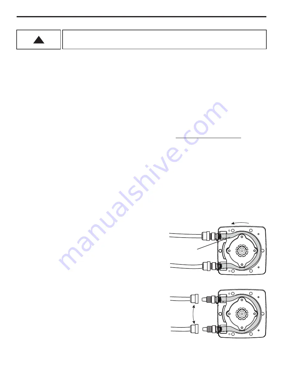
Reverse Rotor Rotation
The pump rotor can reverse rotation by pressing REVERSE ROTATION button.
In most applications, the tube will fail by developing a small leak in the outlet side (pressure side) of the tube
assembly. By reversing the roller rotation, the wear point in the tube is moved to the opposite side ot the pump
tube assembly, increasing the life of the tube.
Swap Inlet
and Outlet
ON
R
T
F
Reversing rotation, moves the outlet side (pressure side) to
the opposite side of the tube assembly, greatly increasing the
tube life.
Stop the pump before the tube failure occurs.
Disconnect power from the pump. Carefully purge any
pressure in the discharge line of the pump. Disconnect the
suction end tubing/piping and the discharge end tubing/piping
from the pump head tubing.
IMPORTANT! Swap sides of the suction (inlet) and discharge
(outlet) tubing/piping. There is no need to remove the Pump
Head Cover.
Double check all connections before starting the pump
NOTE: The pump tube will form a natural U-shaped curve. Do
not attempt to install the pump tube against the natural U-
shape direction as damage to the tube can result.
ON
R
T
F
Outlet
Inlet
D
ir
n
e
o
i
c
t
t
a
i
t
o
o
n
R
Typical Failure Point
(pressure side)


