background image

www.blaubergventilatoren.de

vento expert (Duo) a W v.2

21

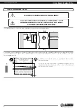
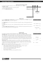
To connect a Master and a Slave unit, set the DIP switches on each ventilator to Master or the Slave position (see page 13).
Then set up the Wi-Fi parameters of the master unit (see page 20).

CONNECTING MASTER AND SLAVE VENTILATORS

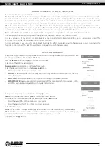
SPECIAL SETUP MODE

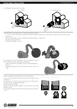
BATTERY REPLACEMENT

Press and hold the 

Ventilation


 button on the Master unit casing. Wait for the beep and the blinking of all the LED lights on the unit 

casing. Repeat the steps with all the Slave units and wait for the beep when all the LED lights go down on each Slave unit. Set the Master 

unit to the standard operation mode. Press and hold the 

Ventilation


 button. Wait for the beep and going down of all the LED lights.

Note: 

If the home router works in conjunction with several Wi-Fi access points and the ventilators require connection to different access 

points:
•  Connect the Master unit to the first Wi-Fi access point.
•  Complete the connection with the first group of Slave units.
•  Connect the Master unit to the second Wi-Fi access point.
•  Complete the connection with the second group of Slave units.

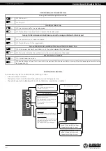
In the event of losing the Wi-Fi password or the Master unit password or in other cases use the recovery Setup mode to restore access 

to the ventilator functions. To enter the special setup mode, press and hold the 

Ventilation


 button on the ventilator casing for 5 

seconds, until the beep and blinking of all the LED lights. 
The ventilator continues in this mode for 3 minutes and then automatically revert to the previous settings. To exit the Setup mode 

immediately, once again press and hold the 

Ventilation


 button on the ventilator casing for 5 seconds, until the beep and shutdown 

of all the LED lights.

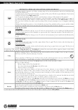
In this mode the following settings are available:
• 

Wi-Fi network name:

 Setup mode.

• 

Wi-Fi password:

 11111111.

• 

The unit password cannot be read.

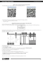
The 

Alarm

 indicator on the ventilator casing blinks, when the battery 

charge is low. The mobile app will also display the 

, warning and 

show the following message on pressing the indicator icon.
Low battery power may cause disruptions in the weekly schedule 
operation. Power off the unit before replacing the battery. After 
replacing the battery re-set the time and date.

The battery is located on the control circuit board. Power off the 
ventilator to replace the battery, remove the front panel and the 
cover protecting the control circuit board. Remove the battery and 
install the new one.

Battery type:

 CR1220.

AFTER CHANGING THE WI-FI PARAMETERS OF THE MASTER VENTILATOR REPEAT THE 

CONNECTION STEPS!

WHILE COMPLETING THE CONNECTION MAKE SURE THAT THE SLAVE UNITS ARE 

WITHIN COVERAGE OF THE BUILT-IN WI-FI IN THE MASTER UNIT

Summary of Contents for Vento Expert A100-1 W V.2

Page 1: ...Single room reversible energy regeneration ventilator USER S MANUAL EN Vento Expert A50 1 W V 2 Vento Expert A85 1 W V 2 Vento Expert A100 1 W V 2 Vento Expert Duo A30 1 W V 2...

Page 2: ...ics design or configuration of its products at any time in order to incorporate the latest technological developments No part of this publication may be reproduced stored in a retrieval system or tran...

Page 3: ...r Protect the electric parts of the unit against ingress of water Do not allow children to operate the unit Disconnect the unit from power mains prior to any technical maintenance Do not store any exp...

Page 4: ...le or explosive mixtures evaporation of chemicals sticky substances fibrous materials coarse dust soot and oil particles or environments favourable for the formation of hazardous substances toxic subs...

Page 5: ...ous parts access and water ingress protection rating is IP24 The unit design is constantly being improved so some models may be slightly different from those ones described in this manual Technical da...

Page 6: ...a matching ventilation hood model Sound absorbing mat Sound insulating material that provides attenuation of operation noises Vento Expert Duo Vento Expert FUNCTIONING OF THE AIR SHUTTERS FOR Vento E...

Page 7: ...ed in the regenerator In 70 seconds after the regenerator cools down the ventilator goes again to the extract mode and the cycle starts from the beginning In this mode in case of installation of two v...

Page 8: ...e air duct in the wall hole For ease of installation use the polystyrene wedges included in the delivery set The air duct end must protrude for the distance A that enables installation of the outer ve...

Page 9: ...bs to detach the front part of the indoor unit from its rear part ATTENTION Prior to mounting the front panel make sure that the thermal actuator rod is in the lowest position Blinking of the white LE...

Page 10: ...tecting paper layer outside Insert the roll in the air duct against stop to the cartridge Make a mark at the end of the air duct remove the sound absorbing mat and cut the roll according to the markin...

Page 11: ...e signal cables The above wire cross section value is tentative The signal cable must be shielded The actual conductor cross section selection must be based on the wire type maximum wire temperature i...

Page 12: ...unit 1 ON Slave unit Standby mode setup 2 OFF the ventilator is off in the Standby mode 2 ON the ventilator is running at the first speed in the Standby mode SetupofairflowdirectioninVentilationmodewi...

Page 13: ...tilation indicates forced activation of the supply ventilation mode of the ventilator This mode may be activated via the mobile application only Filter The filter clogging indicator starts blinking 90...

Page 14: ...tion mode Ventilation mode Vento Expert The ventilator runs in the extract or in the supply mode at the set speed The fan rotation direction depends on the position of the DIP switch 3 Vento Expert Du...

Page 15: ...mobile device to the Wi Fi access point with the name FAN 16 ID Number characters stated on the ventilator casing under the front panel Wi Fi access point password 11111111 1 2 4 5 6 8 7 3 Enter the B...

Page 16: ...the ventilator operation mode 4 hours by default adjustable in the menu Settings Timers DESCRIPTION OF MOBILE APPLICATION INDICATORS Current type of connection to the ventilator Home connection or co...

Page 17: ...n below the set point the turn off delay timer for the Boost mode is activated After the delay timer countdown the ventilator reverts to the previous speed setting Sensor 0 10 V actuation of the analo...

Page 18: ...he date and time The ventilator filters must be serviced after every 90 hours of continuous operation The need to replace the filters is communicated by the indicator in the upper section of the Contr...

Page 19: ...the same speed In case of actuation of any sensors for Vento Expert Duo only the affected ventilator goes to the maximum speed according to the humidity control scenario The rest of the ventilators c...

Page 20: ...the Master unit with its own wireless access point In case of connection of eight Slave units to the Master unit with its own wireless access point a mobile device may not be connected Wiring diagram...

Page 21: ...access to the ventilator functions To enter the special setup mode press and hold the Ventilation button on the ventilator casing for 5 seconds until the beep and blinking of all the LED lights The ve...

Page 22: ...ny loss of Internet connection provided by the home server may result in temporary loss of communication with the ventilator Create a new account for control of the Master ventilator For that open the...

Page 23: ...ndicator glowing goes down AIR FLOW BLOCKING FOR Vento Expert Duo Press the side tabs to detach the front part of the indoor unit from its back part and close the air duct Then open the latches and re...

Page 24: ...il it goes down up to 2 minutes Warning Prior to mounting the front panel make sure that the ther mal rod is in the low position and the indicator of the circuit board glows Vento Expert Duo 1 Press t...

Page 25: ...ular technical maintenance may not completely prevent dirt accumulation on the regenerator and the fans Clean the regenerator regularly to ensure its high regeneration efficiency Clean the regenerator...

Page 26: ...ler is contaminated Clean the impeller Loose screw connection in the ventilator casing or in the outer ventilation hood Tighten the screws of the ventilator or the outer ventilation hood Store the uni...

Page 27: ...manufacturer s warranty does not apply to the following cases User s failure to submit the unit with the entire delivery package as stated in the user s manual including submission with missing compon...

Page 28: ...www blaubergventilatoren de Vento Expert Duo A W V 2 28...

Page 29: ...www blaubergventilatoren de Vento Expert Duo A W V 2 29...

Page 30: ...www blaubergventilatoren de Vento Expert Duo A W V 2 30...

Page 31: ...e of the complete unit delivery with the user s manual The warranty terms are acknowledged and accepted Customer s Signature The Vento Expert _________________ unit has been connected to power mains p...

Page 32: ...www blaubergventilatoren de B133 4EN 04...

Reviews: