background image

www.blaubergventilatoren.de

Solo a35/50/60 S4 Pro r (v.2)

6

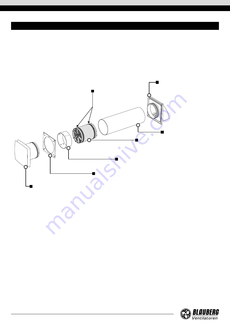
The ventilator consists of an air duct, a ventilation unit and an outer ventilation hood. Two filters, a regenerator, a distance ring and two 
air flow rectifiers are installed in the air duct.
The air filters are designed to purify supply air and prevent foreign object ingress into the regenerator and the fan.
The regenerator utilises extract air heat energy to warm up supply air flow. The regenerator is heat insulated with a specially designed 
insulating material.
The indoor unit with the fan is installed on the inner side of the wall.
The ventilation hood must be installed on the outer side of the wall. It is used for directed air discharge and prevention of ingress of water 
and other objects to the ventilator.

The ventilator operates in two cycles, 60 seconds each.

CYCLE I. 

As warm stale extract air flows through the regenerator, which gradually absorbs heat and humidity. In 60 seconds as the 

regenerator gets warmed up the ventilator is switched to the supply mode.

CYCLE II. 

Fresh intake air from outside flows through the regenerator, absorbs accumulated moisture and is heated to a room temperature 

due to the heat accumulated in the regenerator. In 60 seconds as the ceramic regenerator gets cooled down, the ventilator is switched 
to the air exhaust mode and the cycle is renewed.

DESIGN AND OPERATING PRINCIPLE

Regenerator

Provides extract air energy 
recovery for warming up supply 
air flow.

Filter

Cleans supply air flow and prevents ingress of 

dust and foreign objects into the ventilator.

Prevents contamination of the regenerator.

Outer ventilation hood

Prevents direct ingress of water and 
foreign objects into the ventilator.

Mounting plate

Used for installing the indoor unit on the wall.

Limit ring

Designed to provide the required distance between the 
fan and the regenerator.

Air duct

Indoor unit

Contains a reversible fan that creates air flow.
Has a decorative panel.

Summary of Contents for Solo A35 S4 Pro R

Page 1: ...Single room reversible energy recovery ventilator USER S MANUAL EN Solo A35 S4 Pro R Solo A35 S4 Pro R V 2 Solo A50 S4 Pro R V 2 Solo A60 S4 Pro R V 2...

Page 2: ...ence and knowledge unless they have been given supervision or instruction concerning use of the unit by a person responsible for their safety Children should be supervised to ensure that they do not p...

Page 3: ...tion The casing internals must be free of any foreign objects that can damage the impeller blades While mounting the unit avoid compression of the casing Deformation of the casing may result in motor...

Page 4: ...rated for continuous operation NAME NUMBER Solo A35 S4 Pro R Solo A35 S4 Pro RV 2 Solo A50 S4 Pro RV 2 Solo A60 S4 Pro RV 2 Ventilator 1 pc 1 pc Remote control 1 pc Plastic screwdriver 1 pc Mounting p...

Page 5: ...nst access to hazardous parts and water ingress is IP24 The unit design is constantly being improved thus some models may be different from those described in this manual The technical data of the spe...

Page 6: ...hrough the regenerator which gradually absorbs heat and humidity In 60 seconds as the regenerator gets warmed up the ventilator is switched to the supply mode CYCLEII Fresh intake air from outside flo...

Page 7: ...diameter depends on the specific model of the ventilator and is indicated in the table of overall dimensions in the Technical data section D1 min 300 min 300 min 300 A A A A 2 Install the air duct int...

Page 8: ...screw the self tapping screw from the casing and remove the front part of the indoor unit 5 Attach the mounting plate and mark holes for the dowels with a pencil or marker Drill the holes and insert t...

Page 9: ...mains using a cord with a plug with a switch on the wire Switching from the first speed to the second is carried out only by a standard pull cord switch Speed switch speed I II ON OFF 230 V 50 Hz CONN...

Page 10: ...button on the remote control the ventilator starts to operate at the speed at which it was switched off When switched on using buttons I or II the ventilator starts to operate at the corresponding sp...

Page 11: ...the self tapping screw Remove the four screws retaining the indoor unit then pull it out of the air duct Consequently remove all elements of the ventilator 1 Clean the filters as they get clogged but...

Page 12: ...the power supply line is connected correctly otherwise troubleshoot the connection error The motor is jammed the impeller blades are soiled Turn the ventilator off Troubleshoot the motor jam and the i...

Page 13: ...suitable hoist machinery for handling and storage operations to prevent possible damage to the unit Follow the handling requirements applicable for the particular type of cargo The unit can be carried...

Page 14: ...Contact the Seller for warranty service The manufacturer s warranty does not apply to the following cases User s failure to submit the unit with the entire delivery package as stated in the user s man...

Page 15: ...TION CERTIFICATE The _____________________________________ unit is installed pursuant to the requirements stated in the present user s manual Installation Stamp Company name Address Phone Number Insta...

Page 16: ...www blaubergventilatoren de B132EN 09...

Reviews: