


INSTALLATION
INSTALLATION
7
6
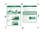
CONNECTING TO YOUR PUMP
The pump supplying the Midipond filter must not have a pumping head exceeding 6m - 0.6 Bar.
The maximum flow rate recommended is stated in the filter performance and specification chart.
This flow should not be exceeded.
The ideal flow rate for your pond is to pump the volume of the pond water through the filter every 2-4
hours. To calculate your pond volume: average length (m) x average width (m) x average depth (m) x
1000 = Litres Pond Volume.
To calculate your pump’s flow rate, fill a container from the outlet hose of the filter at the pond side.
Time how long this takes in seconds e.g. a 10 ltr bucket takes 12 seconds to fill. Divide 3600 (the number of
seconds in an hour) by the time it takes to fill the bucket e.g. 12 seconds. Then multiply by the volume of
the container. e.g. 10 ltr. Therefore - 3600 ÷ 12 = 300 seconds 300 x 10 ltr = 3000 ltrs per hour flow rate.
To increase flow you may need to get a larger pump. If flow is too high use an inline valve to reduce it.
The purpose of the pump is to transfer dirty water from the pond to the Midipond filter.
Placing the pump at the opposite end of the pond to the filter will give the best results.
Foam-free pump designs will give optimum Midipond filtration.
UVC LAMPS & QUARTZ SLEEVE MAINTENANCE
The UVC lamp must be replaced yearly. It is recommended that the lamp is replaced and reconnected in
the spring.
The Quartz sleeve can become coated in lime scale build up in hard water areas. This should be
carefully removed from the quartz sleeve with a soft cloth.
Blagdon Pond Pump Cleaner should be used in stubborn cases.
Remove the quartz sleeve from the unit and soak for 3 hours in Pump Cleaner, ensuring that all O-rings
are checked and replaced, if necessary.
A wet test must be carried out after maintenance to ensure there are no leaks before the UVC is
reconnected.
WET TESTING THE FILTER
IMPORTANT:
A wet test of the filter under operating conditions must be carried out before the
UVC or electrical supply is installed.
Connect the filter to the pump following all installation instructions.
After running for 24 hours check for leaks.
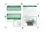
TESTING/REPLACING THE UVC LAMP
IMPORTANT:
Ensure that the mains supply is switched off and the power isolated before removing
the UVC cover.
1.
Unscrew the UVC electronics cover cap.
2.
Inspect the UVC cap and Quartz sleeve for water leaks.
3.
If there are no signs of leakage reverse the procedure ensuring that the Cover o ring is in place.
If there has been any damage to the unit please return to the point of purchase for
inspection. This test should be repeated whenever the the bulb or quartz is changed.
Warning direct exposure to UVC light can damage your eyes or skin.
This unit is protected by a micro switch that prevents the UVC light from
illuminating when the cover is removed even if the power is on.
In order to check that the UVC lamp hold a piece of plain
paper up to the the UVC outlet a faint blue reflection
should be seen. This operation may be needed
to be carried out at dusk as UVC lamps emit
a dim blue light under normal operation.
Electrical installation - UVC
The power supply must meet the specifications on the product.
The UVC is intended to be used with either a weatherproof cable connector or permanently
connected to the fixed wiring in the main system by means of a plug and socket.
The cores in the supply cable are coloured in accordance with the following code:
Brown = Live, Blue = Neutral.
Do not use the supply cable to lift the UVC as this may cause damage.
WARNING -
A Residual Current Device (RCD), also known as the Residual Current Circuit
Breaker (RCCB), with a tripping current not exceeding 30mA must be installed in the supply circuit.
A means of disconnection from the supply having a contact separation of at least 3mm in all
poles must be incorporated in the fixed wiring.
ELECTRICAL INSTALLATION
2
2
3
1
Midipond_Inst_AW.qxd 6/2/07 3:20 pm Page 5