background image

105-A00    page 2/12 

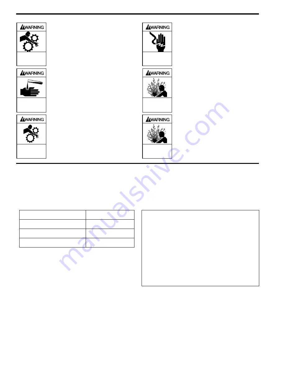
SAFETY DATA 


Hazardous 

machinery can 

cause serious 

personal injury.


FAILURE TO DISCONNNECT AND 
LOCKOUT ELECTRICAL POWER OR 
ENGINE DRIVE BEFORE ATTEMPTING 
MAINTENANCE CAN CAUSE SEVERE 
PERSONAL INJURY OR DEATH 


Hazardous voltage. 

Can shock, burn or 

cause death.


FAILURE TO DISCONNECT AND 
LOCKOUT ELECTRICAL POWER 
BEFORE ATTEMPTING MAINTENANCE 
CAN CAUSE SHOCK, BURNS OR 
DEATH 


Hazardous or toxic 

fluids can cause 

serious injury.


IF PUMPING HAZARDOUS OR TOXIC 
FLUIDS, SYSTEM MUST BE FLUSHED 
AND DECONTAMINATED, INSIDE AND 
OUT, PRIOR TO PERFORMING SERVICE 
OR MAINTENANCE 


Hazardous pressure 

can cause personal 

injury or property 

damage


DISCONNECTING FLUID OR PRESSURE 
CONTAINMENT COMPONENTS DURING 
PUMP OPERATION CAN CAUSE 
SERIOUS PERSONAL INJURY, DEATH 
OR MAJOR PROPERTY DAMAGE.


Do not operate 

without guard  

in place 

OPERATION WITHOUT GUARDS IN 
PLACE CAN CAUSE SERIOUS 
PERSONAL INJURY, MAJOR 
PROPERTY DAMAGE, OR DEATH. 


Hazardous pressure 

can cause personal 

injury or property 

damage 

FAILURE TO RELIEVE SYSTEM 
PRESSURE PRIOR TO PERFORMING 
PUMP SERVICE OR MAINTENANCE 
CAN CAUSE PERSONAL INJURY OR 
PROPERTY DAMAGE. 


PUMP DATA 

 
PUMP IDENTIFICATION 

A pump Identification tag, containing the pump serial number, I.D. number, and model designation, is attached to each pump.  It is 
recommended that the data from this tag be recorded and filed for future reference. If replacement parts are needed, or if 
information pertaining to the pump is required, this data must be furnished to a Blackmer representative. 


TECHNICAL DATA 

Maximum Pump Speed 

870 RPM 

Maximum Operating Temperature 

240°F   (115°C) 

Maximum Differential Pressure 

150 psi   (10.3 Bar) 

Maximum Working Pressure 

350 psi   (24.1 Bar) 

 
Technical Data is for standard materials of construction.  
Consult Blackmer Material Specs for optional materials of 
construction. 

INITIAL PUMP START UP INFORMATION 

Model No.: ____________________________________ 

Serial No.:  ____________________________________ 

ID No.:  _______________________________________ 

Date of Installation: _____________________________ 

Inlet Gauge Reading: ____________________________ 

Discharge Gauge Reading: _______________________ 

Flow Rate: _____________________________________ 


Summary of Contents for XLW1 1/2

Page 1: ...the product or in the manual look for one of the following signal words and be alert to the potential for personal injury death or major property damage Warns of hazards that WILL cause serious person...

Page 2: ...FAILURE TO RELIEVE SYSTEM PRESSURE PRIOR TO PERFORMING PUMP SERVICE OR MAINTENANCE CAN CAUSE PERSONAL INJURY OR PROPERTY DAMAGE PUMP DATA PUMP IDENTIFICATION A pump Identification tag containing the...

Page 3: ...f the pipes Contact the flexible connector hose manufacturer for required maintenance care and design assistance in their use 6 Install pressure gauges in the NPT ports provided in the pump casing to...

Page 4: ...led then reassembled with the shaft on the opposite side of the pump See the Maintenance section for instructions OPERATION Do not operate without guard in place OPERATION WITHOUT GUARDS IN PLACE CAN...

Page 5: ...SHING THE PUMP SOME RESIDUAL FLUID WILL REMAIN IN THE PUMP AND PIPING NOTICE PROPERLY DISPOSE OF ALL WASTE FLUIDS IN ACCORDANCE WITH THE APPROPRIATE CODES AND REGULATIONS PUMP RELIEF VALVE NOTICE THE...

Page 6: ...FLUSHED AND DECONTAMINATED INSIDE AND OUT PRIOR TO PERFORMING SERVICE OR MAINTENANCE NOTICE MAINTENANCE SHALL BE PERFORMED BY QUALIFIED TECHNICIANS ONLY FOLLOWING THE APPROPRIATE PROCEDURES AND WARNIN...

Page 7: ...up the engaged lockwasher tang and rotate the locknut counterclockwise to remove it from the shaft b Slide the lockwasher 24B off the shaft Inspect the lockwasher for damage and replace as required c...

Page 8: ...d shaft into the casing 12 d Install all remaining vanes 14 into the top positions of the rotor 6 Install the disc 71 on the inboard side of the pump with the seal cavity facing outward and the disc r...

Page 9: ...and should be alternately loosened one stop at a time 001 25 microns Begin by loosening the locknut 24A adjusted last 16 Inspect the grease seal 104 for wear or damage and replace as required Grease t...

Page 10: ...ed 6 Vibration from improperly anchored piping 7 Bent shaft or drive coupling misaligned 8 Excessively worn rotor 9 Malfunctioning valve in the system 10 Relief valve setting too low 11 Liner installe...

Page 11: ...105 A00 Page 11 12 NOTES...

Page 12: ...215 GPM HXL 6 8 10 Sliding Vane Pumps 130 to 2 220 GPM Refineries Terminals Barges Ships Reciprocating Gas Compressors Liquefied Gas Transfer Boosting Vapor Recovery Hand Operated Pumps Dispensing Tra...

Reviews: