6
5. To remove locknuts and lockwashers (24A and 24B):
a. Bend up the engaged lockwasher tang and rotate the
locknut counterclockwise to remove it from the shaft
b. Slide the lockwasher (24B) off the shaft. Inspect the
lockwasher for damage and replace as required.
c. Repeat steps a and b on the opposite shaft end.
6. Remove the head capscrews (21). Each head (20) has a
threaded jackscrew hole to facilitate removal. Insert a
capscrew (21) into the jackscrew hole to easily remove
head from the casing (12).
NOTE: It is a good practice
to attach pump heads to the same ends they were
removed from.
7. Slide the head (20) off the shaft. The bearing (24),
mechanical seal stationary seat and stationary O-ring
(153A & 153D) will come off with the head assembly.
a. Pull the bearing (24) from the housing in the head.
b. To remove the mechanical seal stationary seat (153A),
use the blunt end of a screw driver to gently push the
backside of the stationary seat from the head. Place a
cloth under the seal to avoid damage. Be careful not to
contact the polished face of the seal during removal.
Remove and discard mechanical seal stationary O-ring.
8. Carefully pull the rotating seal assembly, consisting of seal
jacket (153C), rotating seal face and rotating O-ring (153B
& 153E) from the shaft. Remove and discard the rotating
O-ring (153E).
9. Carefully remove the disc (71) and head O-ring (72).
10. Pull the rotor and shaft (13) from the casing (12). While
one hand is pulling the shaft, the other hand should be
cupped underneath the rotor to prevent the vanes (14)
from falling out. Carefully set the rotor and shaft (13) aside
for future vane replacement and reassembly.
11. Lay the pump flat with the remaining head facing upward to
remove the head assembly, mechanical seal, and disc from
the outboard side of the pump, as instructed in steps 6 - 9
above.
12. If necessary, remove the liner (41) by tapping around the
outside diameter of the liner with a hard wood drift and a
hammer until it is driven from the casing (12).
PUMP ASSEMBLY
Before reassembling the pump, inspect all component
parts for wear or damage, and replace as required. Wash
out the bearing/seal recess of the head and remove any
burrs or nicks from the rotor and shaft. Remove any
burrs from the liner.
Reassemble the OUTBOARD side of the pump first:
1. Align the liner keyway with the setscrew (74) that extends
down into the pump casing (12) and start the liner (41) into
the casing. The word “INTAKE” cast on the liner must face
the intake port of the pump casing. Uniformly tap the outer
edge of the liner with a rubber mallet to fully insert into the
casing.
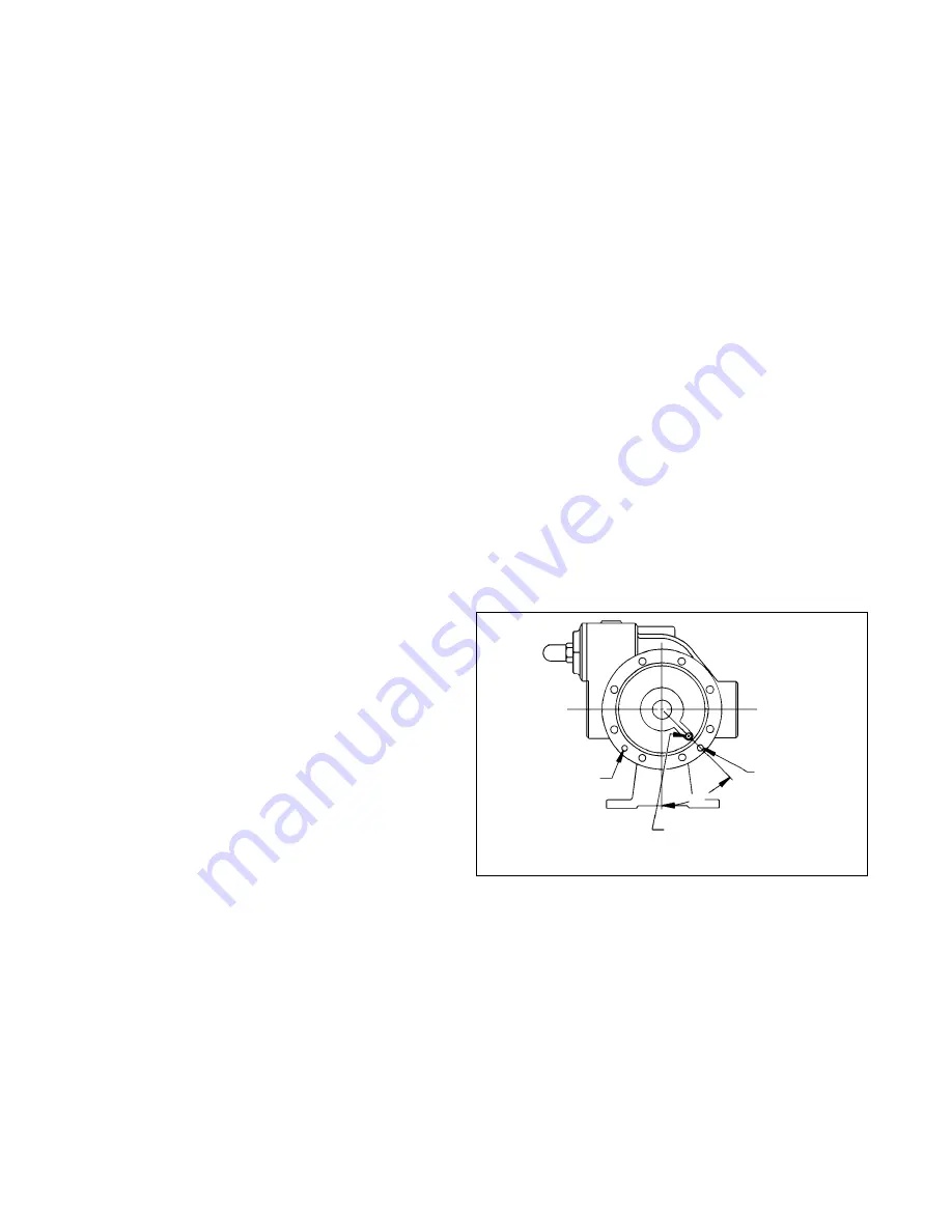
2. Place the disc (71) against the liner (41) with the seal
cavity outward and disc relief hole located as shown in
Figure 5.
MAINTENANCE
3. Without installing the head O-ring (72) or mechanical seal
components, temporarily attach the outboard head (20)
and bearing (24) to the casing (12). Install and hand-
tighten two head capscrews (21), 180 degrees apart. This
head will be used to hold and align the rotor and shaft (13)
while the inboard side of the pump is assembled.
NOTE: It is a good practice to attach pump heads to
the same ends they were removed from.
4. Before installing the rotor & shaft assembly (13), the
direction of pump rotation must be determined as follows:
If the pump is to be
right-hand
with
clockwise
rotation,
the intake port and the relief valve must be on the
right
with the drive end of the shaft pointing towards the
observer.
If the pump is to be
left-hand
with
counterclockwise
rotation, the intake port and the relief valve must be on
the
left
with the drive end of the shaft pointing towards
the observer.
5. Remove the vanes (14) and push rods (77) (if equipped)
from the rotor and shaft assembly (13). Inspect for wear
and damage, and replace as follows:
a. Insert the vanes (14) into the bottom rotor slots with the
relief grooves facing in the direction of pump rotation,
and with the rounded edges outward. See Figure 4.
Figure 5 - Disc Relief Hole Location
DISCHARGE
INTAKE
45
o
Position disc relief hole here.
Locator pin
Locator pin
b. If the pump is equipped with an optional four-vane rotor
and shaft (13A), hold the two bottom vanes (14) in
place while inserting the two push rods (77).
c. After the bottom vanes (14) (and push rods, (77) if
equipped) are installed, carefully insert the non-driven
end of rotor and shaft into the casing (12).
d. Install all remaining vanes (14) into the top positions of
the rotor.
6. Install the disc (71) on the inboard side of the pump with
the seal cavity facing outward and the disc relief hole
located as shown in Figure 5.
7. Install a new head O-ring (72) in the groove between the
disc (71) and the casing(12).


