5
MAINTENANCE
DO NOT ATTEMPT TO OPEN THE PUMP
UNTIL YOU HAVE BLED OFF THE
PRESSURE. ON SYSTEMS WITH
METERS, THE DIFFERENTIAL VALVE
WILL KEEP LIQUID UNDER PRESSURE
IN THE PUMP, METER AND PIPING
EVEN WHEN THE HOSE IS EMPTIED.
Hazardous pressure
can cause personal
injury or property
damage.
DISCONNECTING FLUID OR
PRESSURE CONTAINMENT
COMPONENTS DURING PUMP
OPERATION CAN CAUSE SERIOUS
PERSONAL INJURY, DEATH OR MAJOR
PROPERTY DAMAGE.
Hazardous pressure
can cause personal
injury or property
damage.
Hazardous or toxic
fluids can cause
serious injury.
IF PUMPING HAZARDOUS FLUIDS
SYSTEM MUST BE FLUSHED AND
DECONTAMINATED, INSIDE AND OUT
PRIOR TO PERFORMING SERVICE OR
MAINTENANCE.
LUBRICATION
Ball bearings must be lubricated every three months at a
minimum. More frequent lubrication may be required,
depending on the application and the operating conditions.
Recommended Grease:
Exxon® - RONNEX MP Grease;
Mobil®
MOBILITH AW-2 (64353-6) Grease, or equivalent
Lithium grease.
Greasing Procedure:
1. Remove the grease relief fittings (76A) from the bearing
covers (27, 27A).
2. SLOWLY apply grease with a hand gun until grease begins
to escape from the grease relief fitting port. Discard
excess grease in accordance with the proper codes and
regulations.
3. Replace the grease relief fittings (76A).
DO NOT overgrease pump bearings. While it is normal for
some grease to escape from the grease tell-tale hole after
lubrication, excessive grease can cause mechanical seal
failure. The tell-tale hole is located in the head between the
bearing and the seal.
VANE REPLACEMENT
NOTICE:
MAINTENANCE SHALL BE PERFORMED BY QUALIFIED
TECHNICIANS ONLY, FOLLOWING THE APPROPRIATE
PROCEDURES AND WARNINGS AS PRESENTED IN
THIS MANUAL.
1. Drain and relieve pressure from the pump and system as
required.
2. Remove the head assembly from the
outboard
(non-
driven) side of the pump according to steps 4 - 9 in the
"Pump Disassembly" section of this manual.
3. Turn the shaft by hand until a vane (14) comes to the top
(12 o'clock) position of the rotor. Remove the vane.
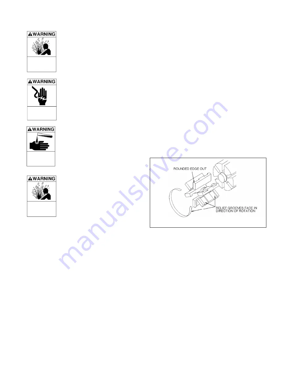
4. Install a new vane (14), ensuring that the rounded edge is
UP, and the relief grooves are facing towards the direction
of rotation. See Figure 4.
4. Repeat steps 3 and 4 until all vanes have been replaced.
NOTE:
The standard rotor & shaft has eight vanes and no
push rods. The optional rotor & shaft has four vanes and
two push rods.
6. Reassemble the pump according to the "Pump Assembly."
section of this manual.
Figure 4 - Vane Installation
FAILURE TO DISCONNECT AND
LOCKOUT ELECTRICAL POWER
BEFORE ATTEMPTING MAINTENANCE
CAN CAUSE SHOCK, BURNS OR
DEATH.
Hazardous voltage.
Can shock, burn
or cause death.
PUMP DISASSEMBLY
1. Drain and relieve pressure from the pump and system as
required.
2. Starting on the
inboard
(driven) end of the pump, clean the
pump shaft thoroughly, making sure the shaft is free of
nicks and burrs. This will prevent damage to the
mechanical seal when the inboard head assembly is
removed.
3. Remove the inboard bearing cover capscrews (28) and
slide the inboard bearing cover (27) and gasket (26) off the
shaft. Discard the bearing cover gasket.
NOTE: On flange mounted pumps, a bracket mount (108)
takes the place of the inboard bearing cover. To
disassemble, take apart the coupling (34) and remove the
mounting screws (28A). The bracket and gasket (26) can
then be removed from the head (20).
4. Remove the outboard bearing cover capscrews (28) and
slide the outboard bearing cover (27A) and gasket (26) off
the shaft. Discard the bearing cover gasket.


