BLACKMER HD172A Installation, Operation & Maintenance Instructions Manual Download Page 8

CB-9A-040     page 8 

INSTALLATION


LOCATION AND PIPING


Compressor life and performance can be significantly reduced when installed in an improperly designed system.  
Before starting layout and installation of the piping system, consider the following suggestions: 

1. 

A strainer should be installed in the inlet line to protect the compressor from foreign matter.  A #30 mesh 
screen or finer is recommended.  Strainers must be cleaned regularly-once every 180 days, or more 
frequently if the system requires. 

2. 

All piping must be leak free to a pressure of 1.5 times the maximum system pressure. 

3. 

Expansion joints, placed within 36" (0.9 m) of the compressor, will compensate for expansion and 
contraction of the pipes. 

4. 

Piping must be well supported so that it does not spring away or drop down when flanges or union joints 
are disconnected. 

5. 

Both suction and discharge piping should slope down from the compressor.  The compressor should not 
be placed at a low point in the piping system. 


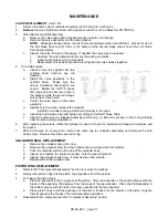
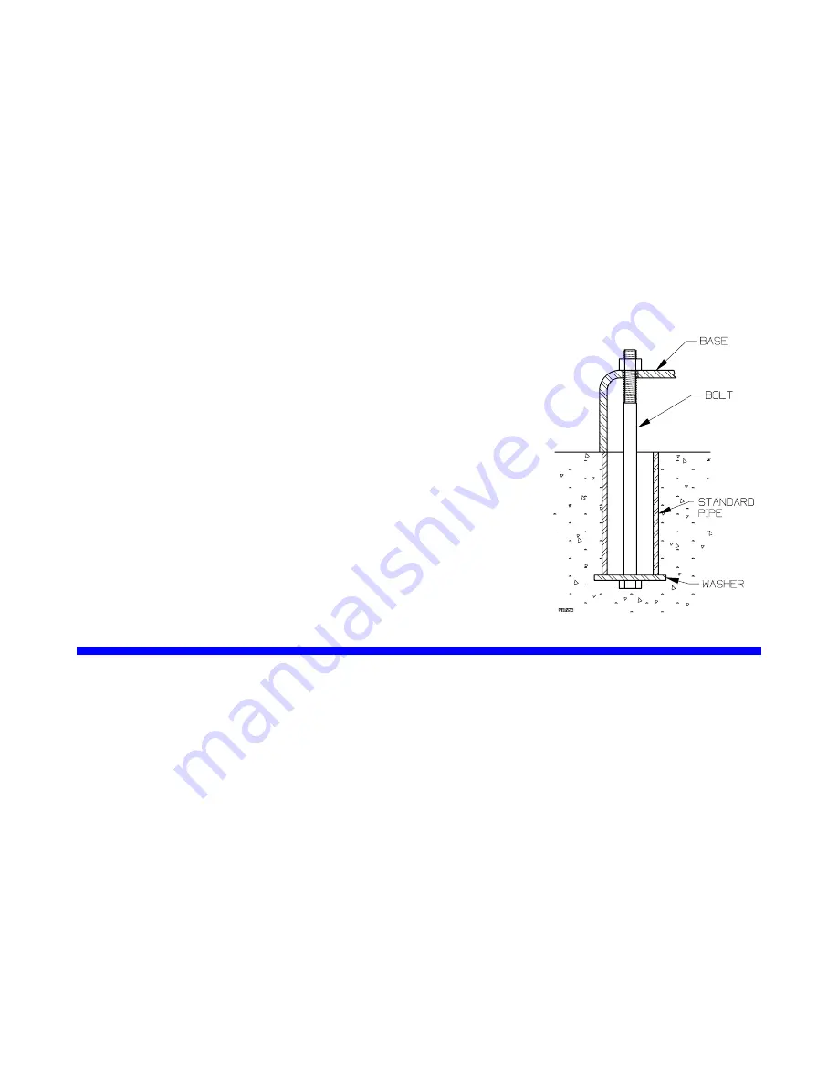
MOUNTING THE COMPRESSOR UNIT


A solid foundation reduces noise and vibration, and will improve 
compressor performance.  On permanent installations it is recommended 
the compressor be secured by anchor bolts as shown.  This arrangement 
allows for slight shifting of position to accommodate alignment with the 
mounting holes in the base plate. 

For new foundations, it is suggested that the anchor bolts be set in 
concrete.  When compressors are to be located on existing concrete floors, 
holes should be drilled into the concrete to hold the anchor bolts.   

NOTE: To keep vibration at a minimum, in addition to a solid concrete 
foundation it is important that the concrete be located on a stable soil 
foundation.  The base should have complete contact along its entire length 
with the foundation.  Visible separations can result in vibrations which are 
magnified in the upper part of the unit. 
 

Pipe Type Anchor Bolt-Box 


OPERATION


PRE-STARTUP CHECK LIST


1. 

After the compressor is installed in the system, a complete leak test should be performed on both the 
compressor and the piping. 

2. 

Check the alignment of the pipes to the compressor.  Pipes should be supported so that they do not spring 
away or drop down when flanges or union joints are disconnected. 

3. 

If V-belt driven, check the alignment of the motor and the compressor sheaves.  The faces of the sheaves 
must be parallel.  

4. 

It is recommended that pressure gauges be installed in the discharge and inlet lines.  These can be used 
to check actual suction and discharge conditions after startup. 

5. 

Check the electrical connections for proper wiring, grounding, etc. 

6. 

Blackmer compressors are shipped from the factory without oil in the crankcase.  Fill with a high quality oil 
of the proper viscosity (see "Lubrication"). 

7. 

Disconnect the power and remove the nameplate.  Squirt oil onto the crosshead guide bores and rotate 
the compressor by hand to verify smooth operation. 

8. 

Ensure that all guards in properly in place. 


Summary of Contents for HD172A

Page 1: ...TICALLY TESTED COMPRESSOR MUST BE ISOLATED WATER ENTERING THE UNIT CAN CAUSE CORROSION AND DAMAGE NOTE NAMEPLATE DATA HERE MODEL HD ID SERIAL NUMBER TABLE OF CONTENTS GENERAL INFORMATION 2 Compressor...

Page 2: ...you should 1 Note the nameplate data in the space provided above 2 Obtain the appropriate parts lists for the model in question 3 These compressors are used on a wide variety of gasses Before doing an...

Page 3: ...5 Glass Moly Filled M Poly Filled PTFE A SEAL PACKING ORIENTATION Field 6 All Lips up 1 Top Lips Down Bottom Up Tube to Stage 1 outlet 2 Top Lips Up Bottom Down 3 Top Lips Down Bottom Up Tube to Stag...

Page 4: ...is suggested that the valves and piston rings be inspected after the first few hundred hours of operation This will give an early indication of any abnormal problems and allow for corrective action to...

Page 5: ...eric Pressure or above Vacuum to 25 psia Under 5 psia Service General Gas Transfer Toxic Flammable or otherwise Hazardous Gases General Gas Transfer Special Upper Distance Piece Connections Plugged Pu...

Page 6: ...CB 9A 040 page 6 GENERAL INFORMATION SEAL ORIENTATION DOUBLE SEAL COMPRESSORS SEAL ORIENTATION ALL TRIPLE SEAL COMPRESSORS...

Page 7: ...l port allowing for the use of an optional electric float switch which provides protection to the compressor by stopping the compressor when a high liquid level is present in the liquid trap The elect...

Page 8: ...hor bolts be set in concrete When compressors are to be located on existing concrete floors holes should be drilled into the concrete to hold the anchor bolts NOTE To keep vibration at a minimum in ad...

Page 9: ...unning time Also retighten all holddown bolts flywheel bolts etc after 60 minutes running time MAINTENANCE MAINTENANCE AND TROUBLESHOOTING MUST BE DONE BY AN INDIVIDUAL EXPERIENCED WITH COMPRESSOR MAI...

Page 10: ...iver Flat Blade Nameplate screws Packing Installation Pliers Rubber Mallet Arbor Press Wrist Pin Removal Bearing Puller Crankshaft Bearings Torque Wrench 0 to 45 ft lb range Various Hoist useful Cylin...

Page 11: ...Y Below 0 F 18 C 0 to 32 F 18 to 0 C 32 to 80 F 0 to 27 C 80 F 27 C and above SAE 5W SAE 10W SAE 20W SAE 30W Series 170A 370A 610A Quarts 2 3 6 To change the oil drain the crankcase then clean the oil...

Page 12: ...the piston rods The upper packing box O rings will slide off with the packing boxes For disassembly of the packing boxes refer to Packing Replacement 11 After removing the packing boxes remove the lo...

Page 13: ...e b Lubricate the inside bore of the crosshead guide with light oil c Set the crosshead guide over the piston rods and the crossheads and slowly lower it against the crankcase Make certain that the cr...

Page 14: ...ue Table in an alternating pattern h It is important that the proper number of shims be installed under the piston To check rotate the flywheel by hand to bring one piston to the top 1 Measure the dis...

Page 15: ...mportant to install the suction and discharge valves in the correct location in the cylinder head NOTE The valves may be removed without removing the cylinder head from the cylinder Be sure to remove...

Page 16: ...r and retainer ring Typical Valve Assemblies 4 To reinstall valves a Install a new valve gasket into the cylinder head remove any old gaskets b Install the valve assembly in the cylinder head Make sur...

Page 17: ...wn screw and tighten according to the Bolt Torque Table f Install the valve cap or unloader assembly and O ring A little oil or grease on the O ring will help hold it in place during installation 5 Af...

Page 18: ...ring Note To ease installation on the second retainer ring use a screwdriver handle and press on the last washer to compress the seal spring slightly c Two seal packing boxes only Insert the oil defl...

Page 19: ...g cone onto each end of the crankshaft with the tapered end outward The bearing race should rest against the shoulder on the crankshaft e Lubricate the bearings with grease 8 Install the crankshaft th...

Page 20: ...mp ring over the rotor Place the cover O ring into the bearing carrier do not place it on the oil pump cover 6 Orient the oil pump cover with the upper direction arrow the one labeled TOP for the prop...

Page 21: ...pressurized to prevent air or moisture from entering the unit NOTICE Tag the unit with a warning that it is pressurized 3 If a purge gas is not available fog oil into the compressor suction while rot...

Page 22: ...9 9 Low Oil Level Check and fill as necessary 10 10 Dirty Inlet Strainer Clean Inlet Strainer Gas Leaking From Crankcase Breather 11 Faulty Worn Packing Replace Packing 12 12 Piston Rod Scored Replace...

Page 23: ...CB 9A 040 page 23 NOTES...

Page 24: ...1809 Century Avenue Grand Rapids Michigan 49503 U S A 616 241 1611 Fax 616 241 3752 1108 So Portland Avenue Oklahoma City 73108 U S A 405 942 6622 Fax 405 942 2855...

Reviews: