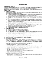
BLACKMER HD172A Installation, Operation & Maintenance Instructions Manual Download Page 22

CB-9A-040     page 22 

TROUBLESHOOTING


PROBLEM


STEP


PROBABLE CAUSE


WHAT TO CHECK


IF PROBLEM 

STILL 

EXISTS GO 
TO STEP ...


Low Transfer 
Rate 

Worn or Broken Piston Rings 

Check condition of rings by restricting 
discharge line.  If pressure increases slowly, 
rings are probably faulty. 


Compressor Valve Faulty 

Remove and inspect for broken or worn 
springs, discs, or bodies. 


Compressor Drive Slipping 

Tighten belts, check for sheared keys, loose 
couplings or flywheel. 


Piping Improperly Designed or 
Installed 

Use proper pipe sizes. 


Knocks or 
Other Noises 

Loose Valves 

Tighten valve hold-down screws. 


Worn Internal Parts 

Inspect through inspection plates and repair as 
necessary. 

No Oil 
Pressure 

Oil Pump Relief Valve Not 
Properly Set. 

Set oil pump relief valve. 


Oil Pump Not Working 

Check the Oil Pump drive tab or stop pin for 
damage. 


Low Oil Level 

Check and fill as necessary 

10 


10 

Dirty Inlet Strainer 

Clean Inlet Strainer 


Gas Leaking 
From 
Crankcase 
Breather 

11 

Faulty/Worn Packing 

Replace Packing. 

12 


12 

Piston Rod Scored 

Replace crosshead assemblies and packing. 

13 


13 

Improper Seal Arrangement 

See "Seal Arrangements". 


Shake or 
Vibration  

14 

Improper Mounting 

Ensure base rails are supported full length (see 
"Mounting the Compressor Unit"). 

15 


15 

Nonfunctioning Valves 

Replace or repair valves. 

16 


16 

Unbalanced Load 

Consult Factory-See Notes Below 


ADDITIONAL NOTES FOR INTERSTAGE PRESSURE: 

Interstage pressure is an important indicator of the proper operation or condition of a two-stage compressor. 
 

*   Low interstage pressure may indicate problems with the first stage valve or piston rings. 


*   High interstage pressure may indicate problems with the second stage valves or piston rings. 

Low compression ratios can cause high interstage pressures.  Two-stage compressors are not normally 
recommended for operation below 5 compression ratios. 


Consult factory for further information


Summary of Contents for HD172A

Page 1: ...TICALLY TESTED COMPRESSOR MUST BE ISOLATED WATER ENTERING THE UNIT CAN CAUSE CORROSION AND DAMAGE NOTE NAMEPLATE DATA HERE MODEL HD ID SERIAL NUMBER TABLE OF CONTENTS GENERAL INFORMATION 2 Compressor...

Page 2: ...you should 1 Note the nameplate data in the space provided above 2 Obtain the appropriate parts lists for the model in question 3 These compressors are used on a wide variety of gasses Before doing an...

Page 3: ...5 Glass Moly Filled M Poly Filled PTFE A SEAL PACKING ORIENTATION Field 6 All Lips up 1 Top Lips Down Bottom Up Tube to Stage 1 outlet 2 Top Lips Up Bottom Down 3 Top Lips Down Bottom Up Tube to Stag...

Page 4: ...is suggested that the valves and piston rings be inspected after the first few hundred hours of operation This will give an early indication of any abnormal problems and allow for corrective action to...

Page 5: ...eric Pressure or above Vacuum to 25 psia Under 5 psia Service General Gas Transfer Toxic Flammable or otherwise Hazardous Gases General Gas Transfer Special Upper Distance Piece Connections Plugged Pu...

Page 6: ...CB 9A 040 page 6 GENERAL INFORMATION SEAL ORIENTATION DOUBLE SEAL COMPRESSORS SEAL ORIENTATION ALL TRIPLE SEAL COMPRESSORS...

Page 7: ...l port allowing for the use of an optional electric float switch which provides protection to the compressor by stopping the compressor when a high liquid level is present in the liquid trap The elect...

Page 8: ...hor bolts be set in concrete When compressors are to be located on existing concrete floors holes should be drilled into the concrete to hold the anchor bolts NOTE To keep vibration at a minimum in ad...

Page 9: ...unning time Also retighten all holddown bolts flywheel bolts etc after 60 minutes running time MAINTENANCE MAINTENANCE AND TROUBLESHOOTING MUST BE DONE BY AN INDIVIDUAL EXPERIENCED WITH COMPRESSOR MAI...

Page 10: ...iver Flat Blade Nameplate screws Packing Installation Pliers Rubber Mallet Arbor Press Wrist Pin Removal Bearing Puller Crankshaft Bearings Torque Wrench 0 to 45 ft lb range Various Hoist useful Cylin...

Page 11: ...Y Below 0 F 18 C 0 to 32 F 18 to 0 C 32 to 80 F 0 to 27 C 80 F 27 C and above SAE 5W SAE 10W SAE 20W SAE 30W Series 170A 370A 610A Quarts 2 3 6 To change the oil drain the crankcase then clean the oil...

Page 12: ...the piston rods The upper packing box O rings will slide off with the packing boxes For disassembly of the packing boxes refer to Packing Replacement 11 After removing the packing boxes remove the lo...

Page 13: ...e b Lubricate the inside bore of the crosshead guide with light oil c Set the crosshead guide over the piston rods and the crossheads and slowly lower it against the crankcase Make certain that the cr...

Page 14: ...ue Table in an alternating pattern h It is important that the proper number of shims be installed under the piston To check rotate the flywheel by hand to bring one piston to the top 1 Measure the dis...

Page 15: ...mportant to install the suction and discharge valves in the correct location in the cylinder head NOTE The valves may be removed without removing the cylinder head from the cylinder Be sure to remove...

Page 16: ...r and retainer ring Typical Valve Assemblies 4 To reinstall valves a Install a new valve gasket into the cylinder head remove any old gaskets b Install the valve assembly in the cylinder head Make sur...

Page 17: ...wn screw and tighten according to the Bolt Torque Table f Install the valve cap or unloader assembly and O ring A little oil or grease on the O ring will help hold it in place during installation 5 Af...

Page 18: ...ring Note To ease installation on the second retainer ring use a screwdriver handle and press on the last washer to compress the seal spring slightly c Two seal packing boxes only Insert the oil defl...

Page 19: ...g cone onto each end of the crankshaft with the tapered end outward The bearing race should rest against the shoulder on the crankshaft e Lubricate the bearings with grease 8 Install the crankshaft th...

Page 20: ...mp ring over the rotor Place the cover O ring into the bearing carrier do not place it on the oil pump cover 6 Orient the oil pump cover with the upper direction arrow the one labeled TOP for the prop...

Page 21: ...pressurized to prevent air or moisture from entering the unit NOTICE Tag the unit with a warning that it is pressurized 3 If a purge gas is not available fog oil into the compressor suction while rot...

Page 22: ...9 9 Low Oil Level Check and fill as necessary 10 10 Dirty Inlet Strainer Clean Inlet Strainer Gas Leaking From Crankcase Breather 11 Faulty Worn Packing Replace Packing 12 12 Piston Rod Scored Replace...

Page 23: ...CB 9A 040 page 23 NOTES...

Page 24: ...1809 Century Avenue Grand Rapids Michigan 49503 U S A 616 241 1611 Fax 616 241 3752 1108 So Portland Avenue Oklahoma City 73108 U S A 405 942 6622 Fax 405 942 2855...

Reviews: