


CB-9A-040 page 17
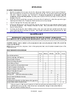
MAINTENANCE
VALVE REPLACEMENT
(size 172)
1.
Remove the valve cap (or unloader assembly) and O-ring from each valve.
2.
Remove
the valve hold down screw with a spanner wrench (such as Blackmer PN 790535).
3.
Valve Removal and Disassembly
a.
Remove the valve cage (and unloader plunger, actuator, and spring).
b.
Remove the valve assembly and the valve gasket.
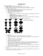
NOTE:
Although visually similar, the first and second stage valves are different. Valves for use in
the first stage have two (2) holes in the bumper while second stage valves have three (3) holes.
See drawing below.
c.
Inspect the valve for wear or breakage. If needed, the valve may be repaired:
1
Unscrew the valve halves and remove the spring and plate.
2
Inspect and replace worn components.
3
Reassemble valves as shown below and tighten the valve halves together.
4. To reinstall valves:
a.
Install a new valve gasket into the
cylinder head (remove any old
gaskets).
b.
Install the valve assembly in the
cylinder head. Make sure the
valve's orientation and location are
correct.
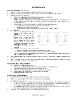
Note:
the HD170 series
first stage valves have two holes in
the bumper while the second stage
valves have three holes.
c.
Center the valve cage on the valve
assembly.
d.
Applies only to suction valves with unloaders.
Install the unloader spring, actuator and plunger in the cage.
e.
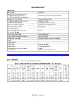
Install the hold down screw and tighten according to the Bolt Torque Table.
f.
Install the valve cap (or unloader assembly) and O-ring. (A little oil or grease on the O-ring will help
hold it in place during installation.)
5.
After replacing the valves, rotate the flywheel by hand to check for interference between the pistons and
the valves.
7.
After 60 minutes of running time, remove the valve cap (or unloader assembly) and retorque the hold
down screw. Replace the valve cap and O-ring.
UNLOADER SEAL REPLACEMENT
a.
Remove the unloader cap and O-ring.
b.
Remove the unloader body from the cylinder head (a strap wrench is helpful).
c.
Push the unloader piston out the top of the unloader body.
d.
Inspect and replace the seals as needed - note the seal orientation!
e.
Inspect the unloader body bore - it must be clean and smooth.
f.
Reassemble in the reverse order.
PISTON RING REPLACEMENT
1.
Refer to the "Compressor Disassembly" section to remove the pistons.
2.
Remove the piston rings and the piston ring expanders from the pistons.
3.
To replace the piston rings:
a.
Place an expander in the top groove of the piston. Place an expander in the second groove with the
break in this expander 180 degrees from the break of the top expander. Place the third expander in
the bottom groove with its break in the same position as the top expander.
b.
Place piston rings in all three grooves of the piston. Make sure the breaks in the piston rings are
directly opposite the breaks in the corresponding expanders.
4.
Reassemble the compressor per the "Compressor Assembly" section.
Summary of Contents for HD172A
Page 23: ...CB 9A 040 page 23 NOTES...


