(11) Inflation
Tire inflation is performed in three steps: BEAD SEAL, BEAD SEAT, and INFLATION. These steps are explained in detail on
page 12. Read the explanation of each step and understand them thoroughly before proceeding.
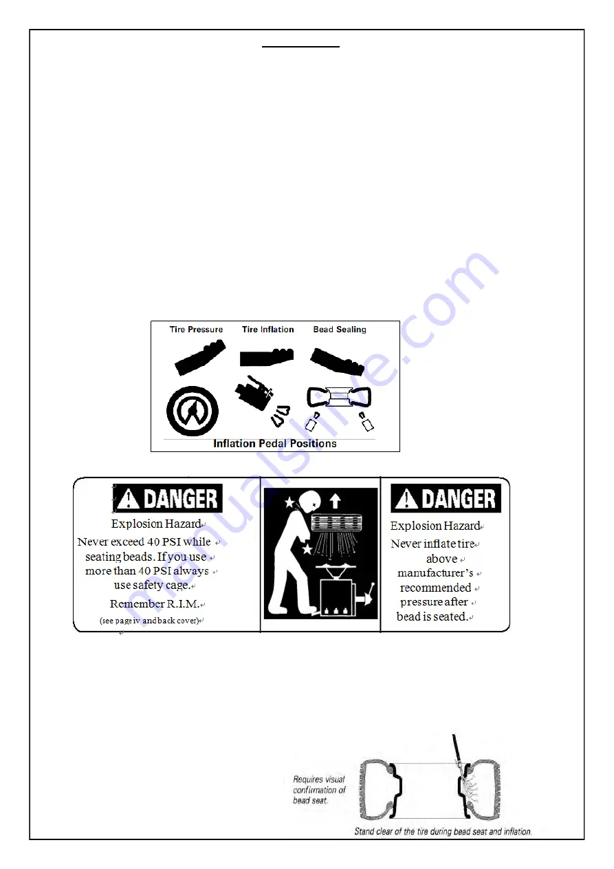
The inflation pedal, located at the rear of the left side of the machine, controls the flow of air through the inflation hose, and
has three positions.
Note:
The clip-on chuck on the end of the hose should always be an open/freeflow style with all parts in
proper working order.
Position 1 - Tire Pressure –
With the inflation hose
attached to the tire valve and the pedal in this position, the air gauge will register the air pressure in the tire. Whenever your
foot is removed from the pedal, it will return to this position.
Position 2 - Tire Inflation –
This is the first activated position. With the inflation hose attached to the tire valve and the
pedal in this position, line pressure is allowed to flow through the valve system and into the tire for inflation. Correct tire
pressure is not indicated on the gauge in this position.
Position 3 - Bead Sealing –
This is the second and last activated position. With the inflation hose attached to the tire
valve and the pedal in this position, line pressure is allowed to flow through the valve and to the airflate bead seal jets on the
table top for bead sealing.
1. If the rim has been clamped from the outside for
tire mounting, release the clamps, lift the tire, and move the clamps to the center of the table top.
Note the Inflation Pedal Positions
(See Diagram)
Stages of Inflation on a Conventional Tire and Rim
Review these descriptions and diagrams carefully. Refer to them as necessary during bead sealing,
bead seating, and inflation to verify that you are proceeding properly and safely.
Bead Sealing
Bead sealing is the process of capturing air pressure between the tire and the rim. The tire will
usually contain about 1/2 to 2 PSI at initial bead seal.
Summary of Contents for TC1024DCA
Page 1: ...TC1024DCA Tire Changer ...
Page 8: ......
Page 11: ...Installation of assist arm Follow the picture to connect the nut and screw ...
Page 19: ...13 Diagram 110V 220V 380V ...


