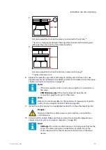
11. Make sure that you use the correct CAN plug for the open CAN OUT socket.
12. CTR201 only: Connect the terminating bias circuit connector to the
corresponding branch of the ISOBUS / power cable (see chapter
on page 24).
13. Make sure that you put protective caps on all the sockets in the control devices
that are not in use (protective caps are included in the delivery).
Power-up the control system
1.
Power-up the control system.
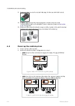
2. Make sure that the system configuration is correct:
• 2WD: No text on the control device segment-display. The green PWR led
flashes.
Figure 9. 2WD: Control device segment-display.
• 4WD: One of the control devices shows A on the segment display and the
other shows B on the segment display. The green PWR led flashes.
Figure 10. 4WD: Control device segment-display.
6.2
Installation and commissioning
30
Product manual

