


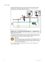


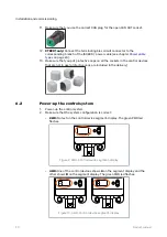


the CVM120/CVU200 valve (2) or to the crane valve (3). If the vehicle has a load-
sensing system, a shuttle valve (4) is also necessary. The shuttle valve lets the
selected valve to control the working pressure level.
LS
P
T
C
4
2
1
3
5
Figure 5. Connection diagram, selector valve.
1 Selector valve
2 CVM120/CVU200
3 Crane valve
4 Shuttle valve
5 Hydraulic lines to the tractor
The CTR101 and CTR201 control systems have an “AUX output” function to control
the external valve from the display. You can use this to control the selector valve. A
maximum permitted current for the valve is 4 A (48 W, 12 V DC)
Attention:
You must connect the pressure inlet port (P) of the CVM120/CVU200 valve
to the de-energized position of the selector valve. The auxiliary valve
output is always de-energized during the driving mode and can energize
only in the freewheeling mode.
You can also use the auxiliary output function for other control purposes in the
maximum current range.
System design
16
Product manual