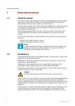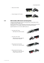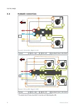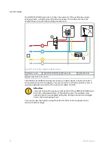
**
Make sure that you verify the rotating direction of the left motor from the
datasheet of the motor. Make sure that you connect the left motor correctly. Refer to
the table that follows for the left motor connections.
***
Driving direction.
Table 1: Connections, motor to valve.
Vehicle side
Motor type
Connections: motor to valve
Right side
1-speed
A to A
B to B
2-speed, CW preferred
A to A
B to B
Left side
1-speed
A to B
B to A
2-speed, CCW preferred
A to A
B to B
Attention:
The direction of rotation of the right motor must be CW.
Do not use 2-speed motors in the CW direction on the left-hand side.
We recommend that you use a Power Beyond hydraulic interface that connects to a
load sensing pump. If it is not available, connect the lines P and T to the tractor
valves.
Note:
The flow direction is from line P to line T.
Attention:
Do not put together lines C and T.
Always connect the line C to the reservoir without valves.
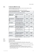
Table 2: Port sizes.
Port
Description
CVM120 valve CVU200 valve
P
Pump - Working pressure inlet
G3/4"
G1"
T
Tank - Return line
G3/4"
G1"
C
Drain – Case leakage
G3/4"
G1"
A1, B1, A2, B2
Working lines for the motors
G1/2"
G3/4"
Y
2-speed function control line
G3/8"
G3/8"
LS
Load-sensing line
G1/4"
G1/4"
MC, MP, M_A2, M_B2
Measurement points for
C, P, A2, B2
G1/4"
G1/4"
Note:
The motor datasheet has the motor port types and the rotating direction.
Selector valve
If you use the same hydraulic supply also to other functions (e.g. crane) with the
drive system, you must usually separate the circuits with a selector valve. An
example of a hydraulic system with a 3/2 selector valve is in the diagram that follows.
In this example the selector valve (1) connects the working pressure (P) line to either
System design
Product manual
15


