21
CHAPTER 3: Installation
Connect each computer CPU to the synchronized Wizard system. First run
cabling from the CPU’s keyboard port, mouse port, and primary video output to
the matching connectors in one of the master Wizard’s “CPU ports.” This cabling
can be either separate male-to-male keyboard-, mouse-, and video-extension cables,
or our three-in-one ServSwitch Duo CPU-Extension Cable. If you need to run
farther than 100 ft. (30.5 m) to a CPU, you’ll need to use one of our ServSwitch
brand KVM extenders.
Finally, connect the additional video outputs from each CPU to the video
connectors in the CPU ports of the additional Wizards. For correct switching,
make
sure
to connect all of the video outputs from the same CPU to same-numbered
ports on your synchronized Wizards. As with your first CPU-video connection,
these connections can be made with video-extension cable or ServSwitch Duo CPU-
Extension Cable for distances up to 100 ft. (30.5 m), or one of our ServSwitch
brand KVM extenders for longer distances.
Feel free to mix computers with multiple video outputs and computers with
single outputs in your synchronized system. When you switch to a CPU with a
single output, that output will be displayed on the first monitor and the additional
monitors will be blank.
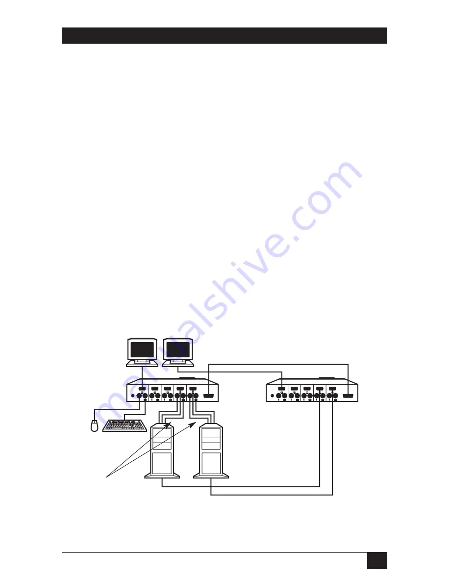
A complete synchronized Wizard system is shown in Figure 3-3.
Figure 3-3. A simple synchronized system with two ServSwitch Wizards.
CPUs
CPU-extension cabling,
including video extension
from CPUs’ first video
output
Video-extension cabling from
CPUs’ second video outputs
Synchronization cable
(DB15 RS-232 extension cable)
First user-
station monitor
Second user-
station monitor
User-station keyboard
and mouse
Master
ServSwitch
Wizard
Additional
synchronized
ServSwitch
Wizard
Summary of Contents for ServSwitch Wizard SW651A
Page 1: ......


