background image



























®

Performing upgrades

The Wizard DVI DL unit is fully upgradeable via flash upgrade. Such upgrades 
require a Windows-based computer system to be linked via the 

OPTIONS

 port. 

Items required to perform an upgrade 

•  Optional serial upgrade cable (see 

Appendix 2

 for pin-out specifications).

•  A Windows-based upgrade computer with an RS232 serial port.
•  The latest version of the KVM Firmware Uploader and firmware files for the 

Wizard DVI DL - contact Black Box technical support. 

To use the KVM Firmware Uploader utility
1 - Obtain and run the KVM Firmware Uploader.

  Download the latest Wizard DVI DL KVM Firmware Uploader (contact Black 

Box technical support) and install it on a Windows-based upgrade computer 
that will be connected to the Wizard DVI DL unit. The files are supplied as a 
compressed ZIP file. Decompress the ZIP file with an appropriate tool such as 
WinZip (www.winzip.com) and copy all contained files to the same folder on 
the upgrade computer. 

2 - Power off the Wizard DVI DL

  Remove the power supply plug from the rear panel of the unit. 

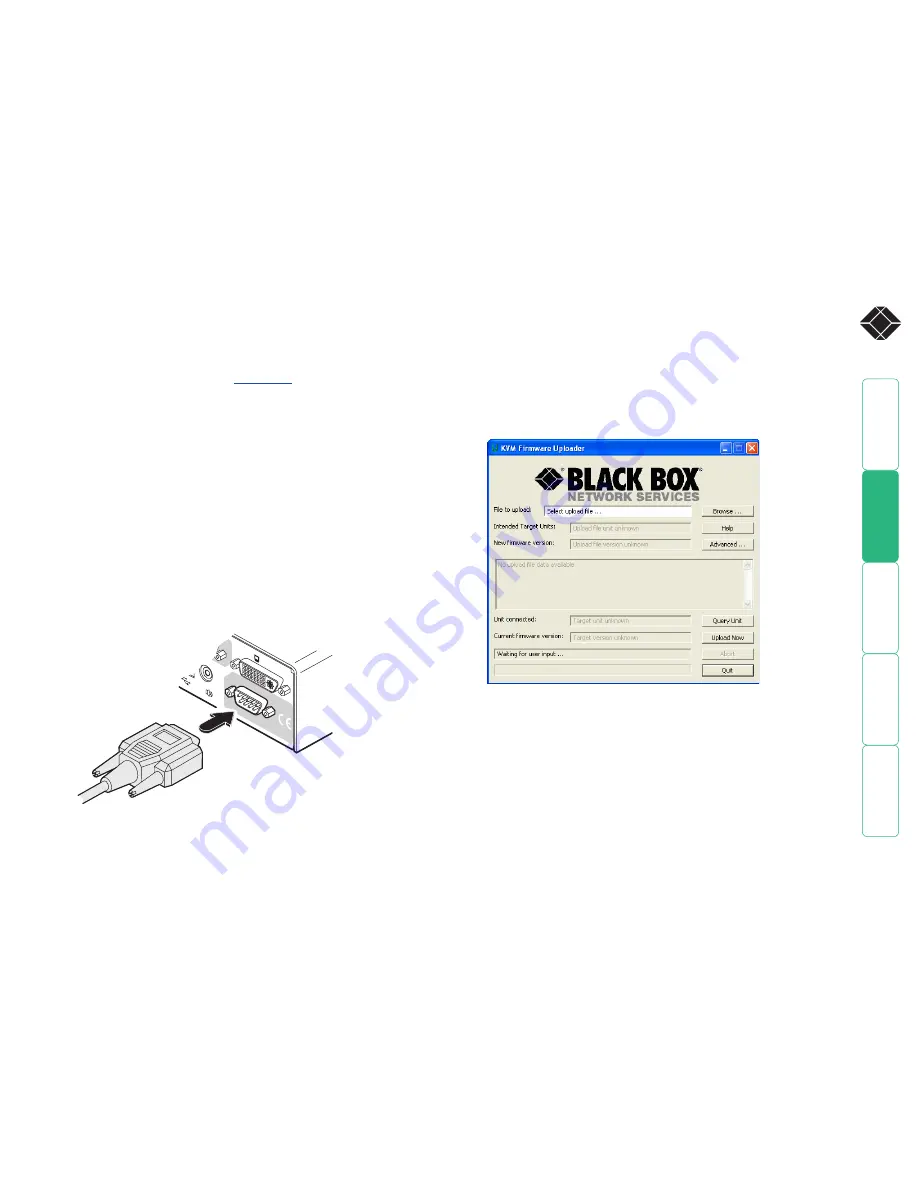
3 - Connect the upgrade computer to the Wizard DVI DL

  Connect the serial port of the upgrade computer to the 

OPTIONS

 port on the 

rear panel of the unit using a null modem serial upgrade cable. 

4 - Invoke upgrade mode

   While powering on or when already powered: Press and hold the 

COMPUTER and MODE buttons (for up to ten seconds) until the numeric 
indicator shows ‘

U

’. The 

UPG

 indicator should also illuminate to show that 

the Wizard DVI DL is ready to be upgraded. 

5 - Run the KVM Firmware Uploader utility

  From that folder, select the KVMUploader icon to run the upgrade utility. 

The KVM Firmware Uploader dialog will be displayed:

6 - Query the Wizard DVI DL

  Click the 

Query Unit

 button to confirm that communication is possible with 

the Wizard DVI DL and to establish its firmware details. If successful, the 
‘Unit connected’ field should show the name of the Wizard DVI DL unit and 
the current firmware will also be listed.

  If the application cannot contact the Wizard DVI DL, re-check the connection 

cable and click the 

Advanced...

 button to check that the correct serial port 

is being used. Change the serial port within the 

Advanced...

 section, if 

necessary.  

continued

OPTIONS

DVI-I

DVI-I

1

  There is no need to adjust the computer’s serial port settings as the 

application will do this automatically.

Summary of Contents for ServSwitch Wizard DVI DL

Page 1: ...technical support 24 hours a day 7 days a week Call 724 746 5500 or fax 724 746 0746 Mailing address Black Box Corporation 1000 Park Drive Lawrence PA 15055 1018 Web site www blackbox com E mail info...

Page 2: ...mputer 16 To select a computer using the on screen menu 16 To select a computer using the front panel 17 To select a computer using the mouse buttons 17 To select a computer using hotkeys 18 Additiona...

Page 3: ...ll characteristics of the connected keyboard and mouse are passed to every system This supersedes the previous method of presenting default identities to the systems which did not allow for specialize...

Page 4: ...ry signals states and processes Therefore manufacturers have previously relied upon a fixed keyboard and mouse profile that is declared to each computer regardless of the actual connected devices This...

Page 5: ...ecting to a computer User console Connect DVI D and or VGA video leads USB keyboard and mouse up to two other USB devices plus optional speakers to these connectors Computer channels Each computer con...

Page 6: ...country specific power lead CD ROM Four self adhesive rubber feet What you may additionally need ServSwitch DVI DL Null modem serial cable 9 way D female to female Two 19 rack mount brackets and four...

Page 7: ...he Wizard DVI DL and its power supply generate heat when in operation and will become warm to the touch Do not enclose them or place them in locations where air cannot circulate to cool the equipment...

Page 8: ...ls If a connected system provides only analogue video then no signal will be seen on the digital DVI D output port and vice versa Attach the lead s from the video monitor to the appropriate port conne...

Page 9: ...5 USB devices Where required attach the leads from your USB peripherals to the USB sockets labeled USB1 and USB2 USB 1 USB 2 DVI I DVI D USER CONSOLE VGA 5V 4A INDOOR USE ONLY 1 2 ON From USB devices...

Page 10: ...IONS DVI I DVI I 1 2 From the USB port on the computer From the video port on the computer From the speaker port on the computer Power in connection The Wizard DVI DL unit is supplied with a standard...

Page 11: ...is fitted with multiple video cards or video cards with multiple video heads Whenever a Wizard DVI DL channel is switched it sends an RS232 command out on the serial interface marked OPTIONS on the re...

Page 12: ...the and keys to highlight an option then press to select Default names for each computer channel Switching mode bar Channel numbers 2 Press To display the Configuration Menu Hotkeys Note and are the s...

Page 13: ...Edit Computer List menu will be displayed 3 Either Create a new computer entry Press and enter a new name or Edit an existing computer entry Highlight a computer name and press Press Backspace to del...

Page 14: ...es option and press to select 4 Select the required option To disable the banner highlight Reminder Banner and press until DISABLED is shown To change colors highlight OSD Color and press repeatedly u...

Page 15: ...e computer to the Wizard DVI DL Connect the serial port of the upgrade computer to the OPTIONS port on the rear panel of the unit using a null modem serial upgrade cable 4 Invoke upgrade mode While po...

Page 16: ...rmware version The upgrade file details will be displayed within the dialog IMPORTANT Check that the Intended Target Units field matches the Unit Connected field If these fields do not match then you...

Page 17: ...F1 More menus F3 Find Esc Quit Tab Cycle Mode Default names for each computer channel Switching mode bar Channel numbers Switching icons show which peripherals are or will be connected to which comput...

Page 18: ...3 Then either Select the channel press the left mouse button Escape without selecting a channel press the right mouse button Depending on the switching mode that has been previously determined using e...

Page 19: ...ects channel 1 Selects channel 2 Selects channel 8 Blanks the video Selects the next channel What are hotkeys The and keys when pressed in combination are called hotkeys and they signal to the Wizard...

Page 20: ...725 92 12 support nederlands blackbox be support french blackbox be support english blackbox be Denmark www blackbox dk 45 56 63 30 10 45 56 65 08 05 support blackbox dk Finland www blackbox fi 35 20...

Page 21: ...d to highlight an option to select an option to change option values to quit and save the changes The following items and menus are available in the Configuration menu Functions Global Preferences Set...

Page 22: ...Returns all key settings within the Wizard DVI DL to their original states WARNING This function will clear all stored computer names When this option is selected you must press the F7 key to confirm...

Page 23: ...be changed Mouse Switching Settings ENABLED DISABLED The computer channel can be switched using a three button mouse or IntelliMouse Pressing the central button or wheel button together with the left...

Page 24: ...oid setting a language that you do not understand as all the menus will change to use the new language and you may have difficulty reselecting your original language Hotkeys Settings CRTL ALT CTRL SHI...

Page 25: ...etermines which monitor connected to the user console should be interrogated to discover its capabilities AUTO first interrogates the DVI port and if no EDID data are available then moves to the VGA p...

Page 26: ...D type female 9pin D type female Multi head synchronization cable MASTER end 9pin D type male SLAVE end 9pin D type male Use this cable when two Wizard DVI DL devices are being synchronized 1 1 DCD DC...

Page 27: ...ser serviceable parts within power adapter do not dismantle Plug the power adapter into a socket outlet close to the module that it is powering Replace the power adapter with a manufacturer approved t...

Page 28: ...is connected d Consult the supplier or an experienced radio TV technician for help FCC Compliance Statement United States This equipment generates uses and can radiate radio frequency energy and if n...

Page 29: ...or los orificios de ventilaci n 10 El equipo el ctrico deber ser situado fuera del alcance de fuentes de calor como radiadores registros de calor estufas u otros aparatos incluyendo amplificadores que...

Page 30: ...ctxd com Documentation by 2009 Black Box Corporation All trademarks are acknowledged Black Box Corporation 1000 Park Drive Lawrence PA 15055 1018 United States of America Tel 1 724 746 5500 Fax 1 724...

Page 31: ...I Indicators 4 K Keyboard connection 7 KVM 2 M Mounting 6 Mouse connection 7 Multiple video head connections 10 synchronisation cable 25 O Operation 16 Options port 4 P Parts supplied and extra 5 Per...

Reviews: