background image

724-746-5500   |   blackbox.com 


Page 35

ACS253A-CT

Chapter 5: Monitor Setup

5. Monitor Setup

This procedure is designed to correct for discrepancies in the video signal from analog/digital video conversion by the monitor. 
You do not need to follow this procedure if you have:

• A CRT monitor connected to the remote unit through the VGA input.

• A TFT monitor connected to the remote unit through the DVI input.'

In these cases, there is no need to adjust the monitor because the video format is not converted.

Make sure that you carry out this procedure before Extender Setup (Chapter 6). If you are using a TFT monitor at the remote 
console with a VGA cable, both the Extender AND the TFT monitor digitize the video data stream and affect video quality. By 
setting up the TFT monitor first, you ensure that you are correcting discrepancies only related to the Extender system in the 
Extender Setup procedure.

1.  Connect the Extender system and display the regular desktop in the desired screen resolution. Monitor setup may vary 

depending on screen resolution and/or refresh rate.

2. Display the OSD utility (see Section 4.1).

3. Select the Tools menu option.

4.  Select the “burst” pattern option. Your TFT should show fine, one-pixel wide, black-and-white vertical stripes over the entire 

screen. The OSD will stay visible in the middle of the screen.

5.  Depending on the type of TFT, press the “AUTO” button on the monitor control panel or select Auto Adjust in the TFT Setup 

Menu. Refer to the manual supplied with your monitor for more information.

6. If the vertical stripes are sharp and without jitter or smearing, the adjustment has been successful. Go to Step 8.

7.  If the picture quality is not acceptable after the automatic adjustment, you will have to manually adjust the pixel clock and pixel 

phase (in this order). Follow the instructions in your monitor’s user manual.

8. Press any key to exit the test pattern display.

9. Exit the OSD.

Summary of Contents for ServSwitch ACS253A-CT

Page 1: ...r toll free in the U S Call 877 877 BBOX outside U S call 724 746 5500 FREE technical support 24 hours a day 7 days a week Call 724 746 5500 or fax 724 746 0746 Mailing address Black Box Corporation 1000 Park Drive Lawrence PA 15055 1018 Web site www blackbox com E mail info blackbox com Customer Support Information ACS253A CT ACS253A U MM R2 ACS253A MM ACS253A U SM R2 ACS253A SM ...

Page 2: ... have any questions about your application or our products contact Black Box Tech Support at 724 746 5500 or go to blackbox com and click on Talk to Black Box You ll be live with one of our technical experts in less than 30 seconds Trademarks Used in this Manual Black Box and the Double Diamond logo are registered trademarks of BB Technologies Inc Mac is a registered trademark of Apple Computer In...

Page 3: ...quipment is operated in a commercial environment Operation of this equipment in a residential area is likely to cause interference in which case the user at his own expense will be required to take whatever measures may be necessary to correct the interference Changes or modifications not expressly approved by the party responsible for compliance could void the user s authority to operate the equi...

Page 4: ...impidan el flujo de aire por los orificios de ventilación 10 El equipo eléctrico deber ser situado fuera del alcance de fuentes de calor como radiadores registros de calor estufas u otros aparatos incluyendo amplificadores que producen calor 11 El aparato eléctrico deberá ser connectado a una fuente de poder sólo del tipo descrito en el instructivo de operación o como se indique en el aparato 12 P...

Page 5: ...power supply if it appears to be defective or has a damaged case Connect all power supplies to grounded outlets In each case ensure that the ground connection is maintained from the outlet socket through to the power supply s AC power input Do not attempt to modify or repair this product or make a connection from the CATx link interface RJ 45 or the fiber link interface SC duplex to any other prod...

Page 6: ...cess Fiber ACS253A U MM R2 and ACS253A U SM R2 Remote and Local Unit Back Panels 18 2 7 Compatibility 20 2 8 Typical Application 20 2 9 How to Use This Guide 21 3 Installation 22 3 1 Interconnection Cable Requirements 22 3 2 System Setup 22 3 3 Diagnostic LEDs 23 3 4 Access Switching 24 3 5 Private Mode 24 4 Device Control 25 4 1 Opening the OSD 25 4 2 Using the OSD 27 5 Monitor Setup 35 6 Extende...

Page 7: ... Refer to the command summary in Chapter 4 when following this procedure Figure QS 1 Quick Setup Instructions Carry out the Monitor Setup procedure see its manual and Chapter 5 in this manual Carry out the VGA Input Setup procedure see Section 6 2 in this manual Install system 1 Connect remote unit to KVM 2 Connect local unit to CPU or switch 3 Connect local and remote units with matching intercon...

Page 8: ...t the highest ranked available combination from the following table Table QS 1 Video Input and Output Video Quality Local Unit Input Remote Unit Output 1 high DVI DVI 2 DVI VGA 3 VGA DVI 4 low VGA VGA QS2 Local Video Output IMPORTANT The local Video Out always carries the same signal your graphics card generates this is opposite of the remote out The local unit does provide any signal translation ...

Page 9: ...ontrol Left Shift I O S D Enter Exit OSD ESC X Select next position Right Arrow R Select previous position Left Arrow L Select submenu Enter S Select parameter modification Enter S Increase parameter Right Arrow R Decrease parameter Left Arrow L Accept and store modified parameter Enter S Back to the menu selection Commands are not case sensitive ...

Page 10: ...solutions operate at 75 Hz Software ACS253A CT Flash ROM for firmware upgrades Connectors ACS253A CT Local unit Keyboard 2 6 pin mini DIN F Mouse 2 6 pin mini DIN F Monitor 2 DVI I F Interconnect 1 RJ 45 Remote unit Keyboard 1 6 pin mini DIN F Mouse 1 6 pin mini DIN F Monitor 1 DVI I F Interconnect 1 RJ 45 ACS253A MM ACS253A SM Local unit Keyboard 2 6 pin mini DIN F Mouse 2 6 pin mini DIN F Monito...

Page 11: ...tment of the video signal is necessary to optimize the analog digital signal conversions DVI KVM Extenders are equipped with various auto matic and manual video correction tools in the OSD 2 2 Terms Used in this Guide The following terms are used in this guide CATx Any Category 5 5e 6 or higher cable Multimode Any multimode duplex cable 50 125μ or 62 5 125μ Single mode Any single mode duplex cable...

Page 12: ...2 Dual Access Multimode ACS253A SM DVI Extender Set PS2 Dual Access Single mode USB Style Kits ACS253A U MM R2 DVI Extender Set USB Dual Access Multimode ACS253A U SM R2 DVI Extender Set USB Dual Access Single mode Upgrade Kits ACS253A AS Audio Serial Upgrade Kit ACS253A TM PS 2 Keyboard Mouse Upgrade Kit for USB devices ACS253A DVI CT DVI Upgrade Kit for Additional Video Channel CATx ACS253A DVI ...

Page 13: ...high power USB devices see Appendix E 1 U S type power cord additional If anything is missing or damaged contact Black Box Technical Support at 724 746 5500 or info blackbox com 2 6 Hardware Description Figures 2 1 through 2 6 illustrate the front and back panels of the ServSwitch KVM Extenders Tables 2 1 through 2 6 describe their components 2 6 1 Front Panel All Models ACS253A CT ACS253A MM ACS2...

Page 14: ...ndicate number of communication errors during previous 60 minutes 4 RJ 45 connector Interconnect carries video and data signals to local unit over CATx cable 5 Link Status LED On when link connection is locked flashing when not connected or not functioning 6 RJ 22 connector Used for firmware upgrades 7 DVI I connector DVI and VGA output connects to remote console monitor 8 Video Signal LED green O...

Page 15: ... cable 14 Link Status LED On when link connection is locked flashing when not connected or not functioning 15 6 pin mini DIN connector Connects to local console mouse 16 6 pin mini DIN connector Connects to local console keyboard 17 6 pin mini DIN connector Connects to CPU s mouse 18 6 pin mini DIN connector Connects to CPU s keyboard 19 4 pin connector Connects to 6 V power supply 20 Device Ready...

Page 16: ... indicate number of communication errors during previous 60 minutes 4 2 SC connectors Interconnect carries video and data signals to local unit over multimode ACS253A MM or single mode ACS253A SM cable 5 Link Status LED On when link connection is locked flashing when not connected or not functioning 6 RJ 22 connector Used for firmware upgrades 7 DVI I connector DVI and VGA output connects to remot...

Page 17: ...CS253A MM or single mode ACS253A SM cable 14 Link Status LED On when link connection is locked flashing when not connected or not functioning 15 6 pin mini DIN connector Connects to local console mouse 16 6 pin mini DIN connector Connects to local console keyboard 17 6 pin mini DIN connector Connects to CPU s mouse 18 6 pin mini DIN connector Connects to CPU s keyboard 19 4 pin connector Connects ...

Page 18: ...power to the USB port s 4 Communication Error LED Flashes to indicate the number of communication errors during previous 60 minutes 5 2 SC connectors Interconnect carries video and data signals to local unit over multimode ACS253A U MM R2 or single mode ACS253A U SM R2 cable 6 Link Status LED On when link connection is locked flashing when not connected or not functioning 7 RJ 22 connector Used fo...

Page 19: ...onnectors Interconnect carries video and data signals to remote unit over multimode ACS253A U MM R2 or single mode ACS253A U SM R2 cable 14 Link Status LED On when link connection is locked flashing when not connected or not functioning 15 1 USB Type A connector Connects to local console keyboard mouse 16 4 pin connector Connects to 6 V power supply 17 Device Ready LED red Lights on when device is...

Page 20: ... CTS DTR DSR In rare cases a wiring adapter may be required to transfer RI and DCD USB compatible to USB 2 0 Full Speed Transmission fully transparent Some USB CD ROM or DVD burning devices may not work properly because of reduced speed Analog Video VGA to UXGA Separate sync composite sync or sync on green Maximum resolution and refresh rates depend on cable length and cable type see Chapter 1 Spe...

Page 21: ...able terminated with RJ 45 plugs to connect the local and remote units Other units require single mode or multimode fibers see Section 3 1 Interconnection Cable Requirements Adjusting Video Because the transmitted signals are digital there is no distortion of video signals or skew problem even with CATx interconnection cables If you do not have a DVI source and a DVI monitor you will need to adjus...

Page 22: ...re 2 1 ACS253A CT Figure 2 3 ACS253A SM MM or Figure 2 5 ACS253A U SM R2 MM R2 NOTE These ports may also be attached to the CPU side of a KVM switch to have a remote CPU However if you are attempting to use the extender between cascaded KVM switches this may not work Contact Black Box Technical Support at 724 746 5500 or info blackbox com to discuss your application 3 C onnect the interconnect cab...

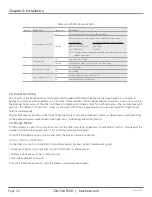
Page 23: ...through 2 6 1 2 5 6 3 4 7 8 Figure 3 1 LEDs on the remote unit Table 3 1 ACS253A remote unit LEDs Number Component Appearance Description 1 Communication Error LED Off No communication errors for more than 60 minutes Flashing Indicates number of communication errors during previous 60 minutes For ACS253A CT For ACS253A xM and ACS253 U xM R2 Slow 10 100 CATx 1 2 Fiber Medium 100 1000 CATx 3 10 Fibe...

Page 24: ...ome first served basis When the keyboard and mouse is in use at one console the Extender blocks access at the other until there is no keyboard or mouse activity for a defined period the inactivity timeout 2 seconds the default or 15 seconds A user can then gain control by any keyboard action or by pressing left and right mouse buttons simultaneously The inactivity timeout period and the choice of ...

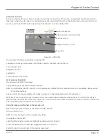
Page 25: ... ways Using the keyboard attached to the Remote Unit NOTE On USB models ACS253 U xx R2 or DVI upgrade kits ACS253A DVI xx keyboard access is not available Please use one of the other methods Using our small windows program with a serial connection to the programming port of the local unit While the OSD is active the mouse is locked and only menu keystrokes are allowed at the keyboard To indicate t...

Page 26: ... 3 Connect the programming cable to the serial port of your computer where the program is running 4 Start the program and follow the on screen instructions 5 Type in the following key sequence O S D followed by ENTER When the OSD starts it displays information about the attached device and firmware version for example Company Name BlackBox Module Name ACS253A 12lo Version Vers 1 3 Date 03 05 15 To...

Page 27: ...et OSD position and size fixed scale sharpness color depth and factory reset 1 Use the left and right arrow keys L and R keys in Windows program to highlight the icon you want The OSD displays additional icons relating to commands in the selected menu category 2 Press the Enter key S key in Windows program The OSD highlights the first command icon 3 Use the Left and Right arrow keys L and R keys i...

Page 28: ...icons used to navigate the OSD utility and to select and adjust the Extender s parameters Table 4 2 OSD parameters Key Icon Remote Keyboard Terminal or Windows program Action Esc X Close the OSD restore normal keyboard and mouse functions Return to the previous Menu selection Enter S Open the highlighted menu or submenu Accept the highlighted command Left arrow L Select the previous menu or comman...

Page 29: ...rated resolution or for example if you have a server farm with many different CPUs each having a different screen resolution With transparent transmission it could take a long time to regain a picture on the screen each time you switch to a different CPU Choice of three fixed transmissions at refresh rate of 60 Hz for LCD flat screens 800 x 600 1024 x 768 or 1280 x 1024 Return to main menu Choice ...

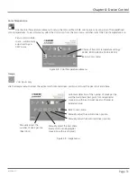
Page 30: ...Color Temperatures Use the Colors menu to adjust the color balance of the video image The menu provides a number of options including automatic calibration manual adjustment in RGB or CMY color space hue and saturation adjustment and the setup of flesh skin tone Automatic color calibration Standard RGB color selection View Color temperature submenu see Color Temperature on the next page Flesh tone...

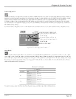
Page 31: ...settings in CMY space Figure 4 8 Color Temperature submenu Image Image VGA inputs only Use the Image menu to adjust the vertical and horizontal screen position and to set the pixel clock and phase Manually adjust the number of pixels per line Pixel clock Automatic detection of the number of pixels per line and the best phase best point for analog digital conversion within each pixel see also Chapt...

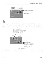
Page 32: ...ss can be affected Use this option to switch between three settings for optimum sharpness Select color depth Display a burst pattern at the remote console for monitor setup Choose whether to automatically adjust pixels per line and pixel phase after a mode change Back to main menu Figure 4 10 Tools menu OSD Use the OSD submenu to define the position and size of the OSD window To view this menu sel...

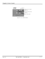
Page 33: ...tection of pixels per line and phase after a mode change Enable Automatic detection of pixels per line and phase after a mode change Back to Tools menu Figure 4 12 Auto Configuration submenu Color Depth Use the Color Depth submenu to select the color depth of the transmitted screen picture Transmissions can be in high color mode or low color mode High color mode produces a better quality image but...

Page 34: ...724 746 5500 blackbox com Page 34 ACS253A CT Chapter 4 Device Control Select low color mode higher fps Select high color mode lower fps Back to Tools menu Figure 4 13 Color Depth submenu ...

Page 35: ...e Extender Setup procedure 1 Connect the Extender system and display the regular desktop in the desired screen resolution Monitor setup may vary depending on screen resolution and or refresh rate 2 Display the OSD utility see Section 4 1 3 Select the Tools menu option 4 Select the burst pattern option Your TFT should show fine one pixel wide black and white vertical stripes over the entire screen ...

Page 36: ...e using a TFT monitor at the remote console with a VGA cable you should carry out the Monitor Setup procedure first see Chapter 5 In this configuration both the Extender AND the TFT digitize the video data stream and affect video quality By setting up the TFT monitor first you ensure that you are correcting discrepancies only related to the Extender system when you re in this procedure Alternative...

Page 37: ...d select the menu command Manually adjust the number of pixels per line pixel clock from the Image menu b Adjust the pixel clock value until all stripes have disappeared c Confirm the setting 9 Problems with the pixel phase will cause horizontal noise horizontal wave formed lines flicker or smearing with a zebra pattern see Figure 6 1 b a From the OSD s Image menu select the menu command Manually ...

Page 38: ...or broken fibers by using a flashlight Fiber models Are the cables of the recommended fiber type If you used your own fiber optic cable not supplied by Black Box make sure that you have used 50μ or 62 5μ fiber with a multimode device or a 9μ fiber with a single mode device Other fiber types and poly fibers are not supported CATx models Check that you have wired the cable straight through Cross pin...

Page 39: ...multaneously this is determined by a jumper setting see Appendix C System Upgrade Dual Access To make a console active we suggest you press and release one of the Shift keys since this will not affect the current PC activity NOTE You cannot gain control if the other console is in use or until the inactivity timeout period has expired 7 3 Contacting Black Box If you determine that your ServSwitch K...

Page 40: ... head application with PS 2 keyboard mouse USB support and audio serial in 19 1U Figure A 3 For more details please discuss suitable extension architecture with Technical Support see Section 7 3 Contacting Black Box CPU USB and graphics output ACS253A U xM R2 Local Unit USB and graphics input from CPU with local console graphics output ACS253A U xM R2 Remote Unit USB and graphics output Local cons...

Page 41: ...udio serial output Local console ACS253A CT Local unit ACS253A CT Remote unit Remote console Figure A 2 CATx application with local access 3 CPUs DVI I USB ACS253A U MM R2 Local unit and RMK253A ACS253A U MM R2 Remote unit and RMK253A 3 remote consoles Figure A 3 Multiple video head application ...

Page 42: ...nking plate Base plate Figure B 1 Rackmounting Kit To mount a unit 1 Align the holes on the base plate with the empty screw holes on the base of the extender unit 2 Fasten the base of the unit to the plate of the mounting kit using the supplied screws 3 Close the remaining gaps with blanking plates The kit enables you to mount various combinations of regular and double width housings Figure B 2 On...

Page 43: ...Page 43 ACS253A CT Appendix B Rackmount Options Figure B 4 Three regular units Figure B 5 One double width unit using wide plate Figure B 6 Double width and regular unit using narrow strip ...

Page 44: ...minimum time of mouse and keyboard inactivity required at one console before the Extender system allows the user at the other console to gain control The upper jumper switch labeled Time selects the inactivity timeout period When closed the setting is 2 seconds When open the setting is 15 seconds Select the method for gaining control Two choices are available Any keyboard activity or by pressing t...

Page 45: ...85 VGA 640 480 31 5 60 25 60 60 60 60 VESA standard 640 480 35 0 66 7 31 67 67 67 67 Industry standard 640 480 37 8 72 31 72 72 36 72 Mac mode 640 480 37 5 75 32 75 75 38 75 VESA standard 640 480 43 2 85 36 85 85 43 85 VESA standard 720 500 31 5 70 28 70 70 70 70 VESA standard 720 400 37 8 85 35 85 85 43 85 PAL progressive 720 576 31 2 50 27 50 50 50 50 VESA guidelines 800 600 35 1 56 56 56 56 28 ...

Page 46: ...temporarily stored DVI VGA by the local unit The data is transmitted using the available net data rate to the remote unit During this time frames generated by the graphics card are discarded without any recognition frame dropping When data transfer is complete the Extender system waits for the next VS signal Depending on the data volume affected by the selected screen resolution refresh rate the t...

Page 47: ... hub The USB specifications allow 100 mA for low power devices 500 mA for high power devices The ACS253A U xx R2 can supply up to 500 mA There is no total power limitation so consuming more than 500 mA may overload the internal power supply and shut down the device This means you can attach either 1 to 4 low power units or 1 high power unit If your total USB power consumption exceeds 500 mA you ne...

Page 48: ...w control on the remote device and PC To do this you will need to construct a custom breakout cable Contact Technical Support at 724 746 5500 or info blackbox com for further information Audio Interface Setup and Operation The audio interface is line level and is designed to take the output from a sound card or other line level source and be connected to a set of powered speakers at the other end ...

Page 49: ...l 1 TMDS data 2 9 TMDS data 1 17 TMDS data 0 2 TMDS data 2 10 TMDS data 1 18 TMDS data 0 3 TMDS data 2 GND 11 TMDS data 1 GND 19 TMDS data 0 GND 4 Not connected 12 Not connected 20 Not connected 5 Not connected 13 Not connected 21 Not connected 6 DDC input SCL 14 5 V power 22 TMDS clock GND 7 DDC output SDA 15 GND 23 TMDS clock 8 Analog VSYNC 16 Hot plug recognition 24 TMDS clock C1 Analog red C3 ...

Page 50: ... 6 pin mini DIN female mouse connector pinning Pin Signal 1 Mouse data 2 Not connected 3 GND 4 5 V 5 Mouse clock 6 Not connected Keyboard In Out Figure G 3 6 pin mini DIN female keyboard connector Table G 3 6 pin mini DIN female keyboard connector pinning Pin Signal 1 Keyboard data 2 Not connected 3 GND 4 5 V 5 Keyboard clock 6 Not connected ...

Page 51: ... 22 programming connector Table G 4 RJ 22 programming connector pinning Pin Signal 1 TxD to PC RxD 2 RxD from PC TxD 3 DTR from PC 4 GND Power Figure G 5 4 pin power connector Table G 5 4 pin power connector pinning Pin Signal 1 GND 2 Earth 3 Not connected 4 6 VDC Housing Shield ...

Page 52: ... G 2 Adapter Cables DVI VGA adapter Remote Local Unit DVI I male connector Figure G 6 DVI I male connector Table G 6 DVI I male connector pinning Pin Signal 6 DDC input SCL 7 DDC output SDA 8 Analog VSYNC C1 Analog red C2 Analog green C3 Analog blue C4 Analog HYSNC C5 Analog GND ...

Page 53: ...Cables Monitor HD15 female connector Figure G 7 HD15 female connector Table G 7 HD15 female connector pinning Pin Signal 15 DDC input SCL 12 DDC output SDA 14 Analog VSYNC 1 Analog red 2 Analog green 3 Analog blue 13 Analog HYSNC 6 7 8 Analog GND ...

Page 54: ...bles Local unit VGA DVI Adapter CPU graphics card HD15 male connector Figure G 8 HD15 male connector Table G 8 HD15 male connector pinning Pin Signal 15 DDC input SCL 12 DDC output SDA 14 Analog VSYNC 1 Analog red 2 Analog green 3 Analog blue 13 Analog HYSNC 6 7 8 Analog GND ...

Page 55: ...G Connectors and Cables Figure G 9 DVI I male connector Table G 9 HD15 male connector pinning Pin Signal 15 DDC input SCL 12 DDC output SDA 14 Analog VSYNC 1 Analog red 2 Analog green 3 Analog blue 13 Analog HYSNC 6 7 8 Analog GND ...

Page 56: ...om ACS253A CT Version 2 About Black Box Black Box provides an extensive range of networking and infrastructure products You ll find everything from cabinets and racks and power and surge protection products to media converters and Ethernet switches all supported by free live 24 7 Tech support available in 30 seconds or less Copyright 2011 Black Box Corporation All rights reserved ...

Reviews: