724-746-5500 | blackbox.com
Page 18
ACS253A-CT
Chapter 2: Overview
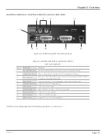
2.6.4 ServSwitch KVM Extender DVI/VGA, USB Dual Access, Fiber (ACS253A-U-MM-R2 and
ACS253A-U-SM-R2) Remote and Local Unit Back Panels
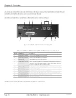
ASC253A-U-MM-R2 or ACS253A-U-SM-R2 Remote Unit Back Panel
1
2 3 4 5 6
7
8
9
10 11
Figure 2-5. ACS253A-U-xM-R2 remote unit back panel.
Table 2-5. ACS253A-U-MM-R2 and ACS253A-U-SM-R2 remote unit components.
Number
Component
Description
1
(2) USB Type A connectors
Connect to USB keyboard/mouse or peripheral
2
(2) USB Type A connectors
Connect to USB keyboard/mouse or peripheral
3
USB power LED
Lights when there is power to the USB port(s)
4
Communication Error LED*
Flashes to indicate the number of communication errors during previous 60 minutes
5
(2) SC connectors
Interconnect—carries video and data signals to local unit over multimode (ACS253A-
U-MM-R2) or single-mode (ACS253A-U-SM-R2) cable
6
Link Status LED*
On when link connection is locked; flashing when not connected or not functioning
7
RJ-22 connector
Used for firmware upgrades
8
DVI-I connector
DVI pr VGA output—connects to remote console monitor
9
Video Signal LED* (green)
On when attached and valid mode detected; off when not attached and detected
10
Device Ready LED* (red)
Lights on when device is ready; off when device is not ready
11
4-pin power connector
Links to 6-V power supply
*NOTE: For more details about the LED indicators, see Table 3-1 in Section 3.3.


