7
CHAPTER 2: Introduction
2.3 Back-Panel Components
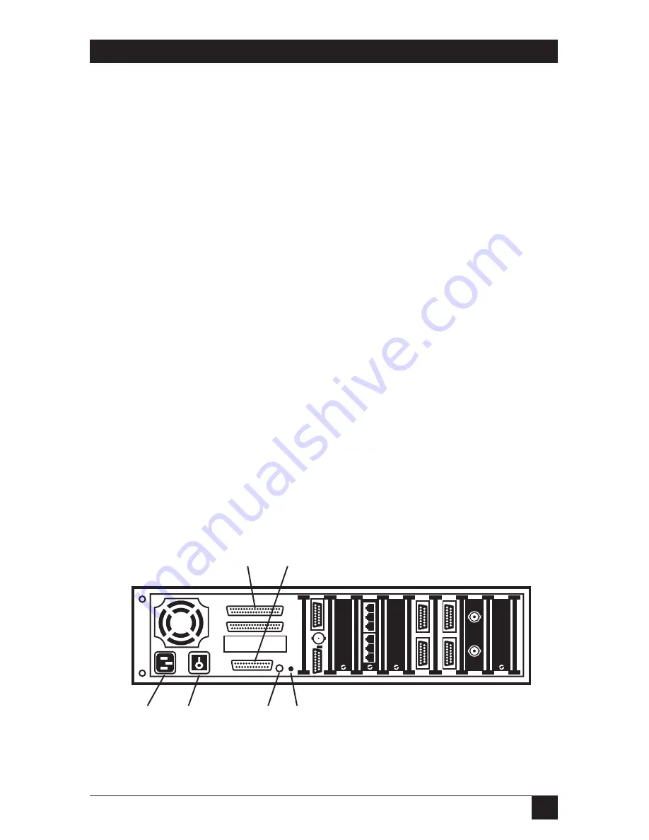
This section describes the back panel components of the RISC Router
Expandable. The numbers in Figure 2-2 correspond to the numbered
descriptions below:
1. AC Power Port —
The AC power port is a three-pronged grounded AC
input port for the RISC Router Expandable. The unit uses 110 or 220
VAC and automatically configures to the appropriate voltage.
2. ON/OFF Switch —
The ON/OFF switch provides power to the RISC
Router Expandable. The “1” indicates ON. The “0” indicates OFF.
3. Reset Switch —
The switch is reserved for future use.
4. FAULT LED —
The FAULT LED (amber) indicates a software problem.
The software triggers a hardware timer once a second. If it fails to do so,
the FAULT LED lights. This LED is the same as the FAULT LED on the
front of the RISC Router Expandable.
5. Wide Area Network (WAN) Port(s) —
The two WAN ports provide
remote transparent bridging. Each WAN port has a male DB37
connector. You can jumper the signaling on the two ports to meet either
RS-423/RS-232, RS-422, or V.35. The signal definitions for the EIA-530
specification follow the RS-422 specification. The V.35-compatible
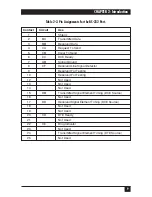
interface is typically an M-block connector. The pin assignments for
these connectors are in Table 2-1.
6. RS-232 Serial Port —
The RS-232 serial port is a DB25 connector used
to provide access to the Network Control program via VT100 compatible
terminal. The pin assignments used in the RISC Router Expandable
RS-232 port are listed in Table 2-2.
Figure 2-2. Back Panel of the RISC Router Expandable.
1
2
3
4
5
6
Summary of Contents for LR5000A
Page 2: ......


