17
CHAPTER 3: Installation
3.4 Network Installation
Determine the configuration of your network and the type of interfaces your
users require. The installation procedures are based on the type of interface.
Refer to the appropriate section for the type of interface ou are using. The
RISC Router Expandable automatically configures to the type of interface.
CAUTION
Be sure to remove the power cord from the back of the RISC Router
Expandable before you install any cables.
3.4.1 C
ONNECTING AN
RS-232 T
ERMINAL TO THE
C
ONTROL PORT
To view the network management software of the RISC Router Expandable,
you must attach a VT100 compatible ASCII terminal to the RS-232 port.
The software provides the user interface to all the configurable parameters
of the RISC Router Expandable. Set your terminal to match the following
RS-232 interface defaults: 9600 baud, one stop bit, no parity.
1.
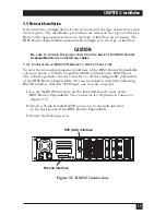
Locate theRS-232 interface on the lower-left-hand corner of the
RISC Router Expandable. The connector is a 25-pin male connector
(Figure 3-7).
2.
Attach a 25-pin female RS-232 connector to the male interface
on the back panel of the RISC Router Expandable.
3.
Secure the locking screws.
Figure 3-7. RS-232 Connection.
RS-232 Interface
DTE (AUI) Interface
Summary of Contents for LR5000A
Page 2: ......


