Black Box LB3104A series Configuration Manual Download Page 14

CHAPTER 1:  Introduction

11

1.5 Ethernet Extender Applications

The Ethernet Extender can be used in a large variety of applications. Some examples follow.

1.5.1 B

RIDGING

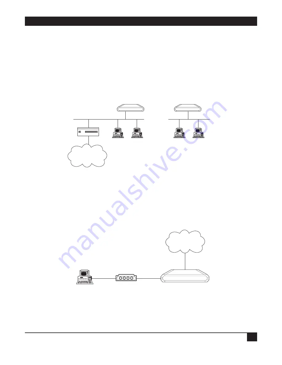
Two Ethernet Extenders can be used opposite each other in a standard bridging application. The Ethernet
Extender connected to the larger network or to a network with connections to other networks, is the Main
Ethernet Extender. The Ethernet Extender connected to the smaller network is the Remote Ethernet Extender.
Refer to Figure 1-4.

Figure 1-4. Standard Bridging Application.

1.5.2 4-W

IRE

M

ODEM

The Ethernet Extender has a built-in 4-wire modem and can be used for one or more PCs to connect to each
other or to the Internet. Refer to Figure 1-5.

Figure 1-5. Connecting to the Ethernet Extender via a 4-Wire Modem.

4-Wire Modem

4-Wire Modem

Ethernet Extender

PC

Internet

Internet

Router

Ethernet Extender

Ethernet Extender

Remote

Main

Summary of Contents for LB3104A series

Page 1: ...1000 Park Drive Lawrence PA 15055 1018 724 746 5500 Fax 724 746 0746 Copyright 1998 Black Box Corporation All rights reserved ...

Page 2: ...ER SUPPORT INFORMATION AUGUST 1998 LB3104A AUI R3 LB3135A AUI R3 LB3804A AUI R3 LB3835A AUI R3 LB3104A BNC R3 LB3135A BNC R3 LB3804A BNC R3 LB3835A BNC R3 LB3104A BT R3 LB3135A BT R3 LB3804A BT R3 LB3835A BT R3 LB3124A AUI R3 LB3136A AUI R3 LB3824A AUI R3 LB3836A AUI R3 LB3124A BNC R3 LB3136A BNC R3 LB3824A BNC R3 LB3836A BNC R3 LB3124A BT R3 LB3136A BT R3 LB3824A BT R3 LB3836A BT R3 Ethernet Exte...

Page 3: ......

Page 4: ...perated in a commercial environment Operation of this equipment in a residential area is likely to cause interference in which case the user at his own expense will be required to take whatever measures may be necessary to correct the interference Changes or modifications not expressly approved by the party responsible for compliance could void the user s authority to operate the equipment This di...

Page 5: ...el flujo de aire por los orificios de ventilación 10 El equipo eléctrico deber ser situado fuera del alcance de fuentes de calor como radiadores registros de calor estufas u otros aparatos incluyendo amplificadores que producen calor 11 El aparato eléctrico deberá ser connectado a una fuente de poder sólo del tipo descrito en el instructivo de operación o como se indique en el aparato 12 Precaució...

Page 6: ... the trademark owners Telecommunication Safety The safety status of each of the ports on the Ethernet Extender is declared according to EN 41003 and is detailed in the table below Safety Status Ports SELV V 24 V 35 V 36 LAN TNV 1 4W SELV Safety Extra Low Voltage TNV 1 Telecommunications Network Voltage within the limits of SELV and subject to overvoltages ...

Page 7: ... Public IP Net 13 2 1 2 Connecting to the Internet Intranet as a Private IP Net Using Single IP 14 2 2 Initial Setup 15 2 2 1 Connecting to the Terminal 15 2 2 2 Setting a Password 16 2 2 3 Changing and Deleting the Password 16 2 3 The Quick Setup Menu 17 2 4 Menus and Screens 17 2 4 1 The Main Menu 17 2 4 2 Quick Setup 17 2 4 3 Security Setup 17 2 4 4 Advanced Menu 18 2 4 5 View 18 2 4 6 Diagnost...

Page 8: ...9 A 1 Which ISDN Service Should You Order 89 A 2 Ordering ISDN 89 A 3 Provisioning ISDN 89 A 4 ISDN Parameters 89 Appendix B BOOT Manager 92 B 1 Preface 92 B 2 Accessing BOOT Manager 92 B 2 1 Access via Software Download Menu 92 B 2 2 Rescue 93 B 3 The BOOT Manager Menu 93 B 3 1 Load New Software 94 B 3 2 Partitions Status 94 B 3 3 Run Second Partition 94 B 3 4 Reactivate Second Partition 95 B 3 5...

Page 9: ...nd IP IPX routers for the small office Quick setup and advanced configuration menus provide on screen instructions that guide you through the configuration procedures The Ethernet Extender features Bridging IP Routing IPX Routing Address Translation Firewall Bridging The Ethernet Extender supports standard bridging functions Because bridging is the Ethernet Extender s default you can use the Ether...

Page 10: ...e Ethernet Extender Normally a LAN requires a complete statically assigned unique and legal subnet with one IP address for every station in order to connect to the Internet or Intranet Single IP allows an entire small office to connect to the Internet or corporate intranet using only one dynamically or statically assigned IP address received from the ISP via a dial up modem ISDN connection leased ...

Page 11: ... Allows a small office to connect to the Internet Intranet in the same way as a single PC Requires only one legal IP address Obtains a single legal IP address from the Internet Intranet Access Router using standard IPCP Allows a small office to access any public IP subnet Allows Web browsing FTP Telnet e mail news and other IP applications using any TCP IP stack on any type of station in the small...

Page 12: ...ction through another firewall using the same mechanism is also allowed 1 3 Solid Firewall The Solid Firewall feature prevents access from the Internet Intranet into the small office LAN This feature makes the small office LAN invisible to outside users The Solid Firewall feature is a simple and foolproof way of protecting security sensitive small offices for example doctors and lawyers from Inter...

Page 13: ...re downloading is available using XMODEM or TFTP Refer to Chapter 5 Dual image flash enables downloading two software versions Refer to Chapter 5 Independent ISDN code downloading is available using XMODEM Refer to Chapter 5 Indicates ISDN link integrity Refer to Chapter 5 Connection on Demand feature reduces WAN costs Refer to Chapter 5 PAP CHAP provides access authentication Refer to Chapter 5 S...

Page 14: ...other networks is the Main Ethernet Extender The Ethernet Extender connected to the smaller network is the Remote Ethernet Extender Refer to Figure 1 4 Figure 1 4 Standard Bridging Application 1 5 2 4 WIRE MODEM The Ethernet Extender has a built in 4 wire modem and can be used for one or more PCs to connect to each other or to the Internet Refer to Figure 1 5 Figure 1 5 Connecting to the Ethernet ...

Page 15: ... point of presence on the Internet A home user can dial in to the Ethernet Extender and use the Ethernet Extender Single IP feature to access the Internet Refer to Figure 1 6 Figure 1 6 Ethernet Extender Using Single IP Internet ISP WAN Home User Solid Firewall Single IP Enabled Ethernet Extender ...

Page 16: ...mation refer to the Ethernet Extender Installation and Operation Guide Before you configure the Ethernet Extender as a router follow the appropriate checklists listed below NOTE If you are using the Ethernet Extender as a router set the location switch to Main For more information refer to the Ethernet Extender Installation and Operation Guide 2 1 1 CONNECTING TO THE INTERNET INTRANET AS A PUBLIC ...

Page 17: ...e LAN Reference RFC 1918 Request a dialup telephone number your username and your password from the ISP Configure this into the Ethernet Extender using the Quick Setup option Check whether a login script is necessary to access the ISP If it is call Technical Support Enable the Single IP in the Ethernet Extender Setup option Make sure the line ISDN PSTN Frame Relay or DDS to the ISP is working prop...

Page 18: ...n menu 2 2 1 CONNECTING TO THE TERMINAL To connect the terminal 1 Connect a control cable between the Ethernet Extender RJ 45 CONTROL port and the connector on the terminal or between the Ethernet Extender RJ 45 CONTROL port and the PC communication port refer to Figure 2 1 2 Set the terminal to work at any baud rate from 2 4 to 19 2 kbps no parity 8 data bits The baud rate is self adaptable 3 Set...

Page 19: ... THE PASSWORD To change the password during normal operation 1 From the Main menu select option 0 Exit to return to the Operational Status Messages screen 2 Press ENTER several times You will be prompted to enter the current password 3 Enter the current password A message appears asking if you want to update the current password Type Y You will be prompted to re enter the current password 4 Re ent...

Page 20: ...of the available Ethernet Extender menus and screens 2 4 1 THE MAIN MENU The name of the device Ethernet Extender connected to the terminal is listed at the top of the screen The Main menu has five options To choose an option you type the number preceding the option MAIN MENU Device name Name 1 Quick setup 2 Security setup 3 Advanced setup 4 View 5 Diagnostic tools 0 Exit Figure 2 2 Ethernet Exten...

Page 21: ...u 2 4 5 VIEW Use the options in the View menu to view configuration screens and information on interface connections routing tables and statistics 2 4 6 DIAGNOSTIC TOOLS Use the Diagnostic Tools menu to verify WAN and LAN connectivity The Ping feature allows you to dial Ping another user on the LAN or WAN If the remote user replies WAN connectivity is confirmed up to and including the IP level 2 4...

Page 22: ...ort you are configuring and how you have already configured other ports To accept the current parameter press ENTER The parameter options are enclosed in brackets To view the options toggle with the space bar and press ENTER To enter new information type in the new parameters and press ENTER After all parameters have been accepted or changed you can view them on the screen A confirmation message a...

Page 23: ... ROUTER Protocol SLIP WAN IP address 0 0 0 0 enter new 0 0 0 0 BOOTP address 0 0 0 0 enter new 0 0 0 0 Modem type Direct Connection Do you want to change modem type Y N N Baud rate 57 6 Kbps Host IP setup LAN IP address 192 168 218 1 enter new 192 168 218 1 LAN IP mask 255 255 255 000 enter new 255 255 255 000 Default gateway setting by Interface Default gateway interface 1 SECURITY setup Device a...

Page 24: ...Address features and eliminates the corresponding parameters from the screen 3 1 3 CONNECTION Select this parameter to determine when the link between the local LAN and the Internet should be activated Selecting upon traffic to WAN activates the link only when there is traffic to be sent on the link Selecting always keeps the link active independent of traffic If you pay for your connection by the...

Page 25: ...s identifies the host is dependent of the class There are 5 classes of IP addresses Each class represents a network having a certain number of computers For example a Class C address is given to a network having from 1 to 255 computers Table 3 1 gives the ranges for different classes of IP addresses Table 3 1 IP Classes Class Range A 0 0 0 0 to 127 255 255 255 B 128 0 0 0 to 191 255 255 255 C 192 ...

Page 26: ... parameter to display the name assigned to the Ethernet Extender for identification by the Internet service provider To change the device access name type in the new name and press ENTER Device Access Password Select this parameter to assign or update a password The password is used to access the Internet The Ethernet Extender s default setup does not include a password Use the space bar to toggle...

Page 27: ...t of the Ethernet Extender and entry to your Chapter 4 Security Setup Menu LAN by unauthorized users Change the Ethernet Extender configuration parameters and Chapter 5 Advanced Setup Menu perform advanced configuration operations not available through the Quick Setup menu reset the device or download software ...

Page 28: ... via SNMP TELNET and Web browsers The Solid Firewall is used to protect the LAN against undesired entry To access the Security Setup menu 1 In the Main menu press 2 The following screen appears SECURITY SETUP Device name Name 1 TELNET access Disabled 2 SNMP access Disabled 3 FIREWALL options Disabled ESC Return to previous menu Choose one of the above Diagnostic Tools 5 View 4 Advanced Setup 3 Sec...

Page 29: ... the Ethernet Extender via TELNET To enable TELNET access 1 From the Main menu select option 2 Security Setup 2 From the Security Setup menu select option 1 TELNET access TELNET access setup ENTER Accept parameter SPACE Change parameter Do you want to permit TELNET management of the device Y TELNET user name lan Do you want to change TELNET password N Y Current password Enter new password Enter ne...

Page 30: ...menu select option 2 Security Setup 2 From the Security Setup menu select option 2 SNMP access 3 Toggle to Y 4 Press ENTER 5 Enter the read write and trap communities Save the new setup SNMP access setup ENTER Accept parameter SPACE Change parameter Do you want to permit SNMP management of the device N Y SNMP read community public SNMP write community private SNMP trap community public Do you want...

Page 31: ...d Firewall is always enabled by default and cannot be disabled To enable the Solid Firewall feature in regular router mode 1 From the Main menu select option 2 Security Setup 2 From the Security Setup menu select option 3 Firewall Options FIREWALL options setup Enabling FIREWALL will forward outgoing sessions from LAN to WAN and block incoming sessions from entering the LAN except for applications...

Page 32: ...pplication toggle the SPACE bar 3 If a specific application has a specific IP destination on the LAN select DEFAULT and type the IP destination address 4 The advanced option includes the following possibilities for forwarding an IP session to the secured LAN Host IP address interval range of destination addresses on the LAN only one address for Single IP Guest IP address interval range of source a...

Page 33: ...t Extender and download software Figure 5 1 Advanced Menu Outline 5 1 Advanced Menu and Setup Menu To access the Advanced menu In the Main menu press 3 The Advanced menu appears ADVANCED MENU Device name Name 1 Setup 2 Device control ESC Return to previous menu Choose on of the above Figure 5 2 Ethernet Extender Advanced Menu The options in the Advanced menu are described below Setup Select this o...

Page 34: ... detailed description of the sub menus refer to the sections that follow HOST PARAMETERS Select this option to enter reference information about the device the IP Host the SNMP agent and TFTP ROUTING BRIDGING Select this option to enter routing or bridging information for the device INTERFACE PARAMETERS Select this option to set link ISDN or Frame Relay parameters ACCESS CONTROL SECURITY Select th...

Page 35: ...Host Parameters menu appears HOST PARAMETERS Device name Name 1 Device ID 2 IP host 3 SNMP manager table 4 TFTP 5 RADIUS ESC Return to previous menu Choose one of the above Device Control 2 Setup 1 Advanced Menu Device Control 1 IP Host 2 SNMP Manager Table 3 TFTP 4 RADIUS 5 1 Device Name 1 IP Address 1 Manager Table 1 File Server IP Address 1 Radius Server IP Address 2 Contact Person 2 IP Mask 2 ...

Page 36: ...P HOST Select this option to configure the following IP parameters IP Address Every device on a TCP IP network must have an address to identify it The IP address is a value consisting of the network address and the host address on that network The value assigned to a network depends on the number of computers on that network The IP address is a 32 bit number The number is made up of 4 parts with e...

Page 37: ...5 255 The default IP mask can be edited Default Gateway The default gateway is the address to which frames are sent if no other address is defined in the routing table The station compares the destination IP address net ID with the station s own net ID If they are not the same the Ethernet Extender automatically sends the packets to the default gateway MAC address in this case the Ethernet Extende...

Page 38: ...rrency to allow multiple users to boot up simultaneously To do this TFTP creates a UDP port for each client By creating a UDP port the different client input datagrams can be demultiplexed by the server s UDP module Demultiplexing in the module increases the server efficiency One characteristic of TFTP is that it is not secure There is no password or firewall associated with TFTP Anyone with the I...

Page 39: ...server to authenticate users Although the term RADIUS refers to the network protocol that the client and server use to communicate it is often used to refer to the entire client server system The three main functions of RADIUS are authentication authorization and accounting To perform these functions you must configure the following parameters Figure 5 7 Setting up the RADIUS Server TFTP Server IP...

Page 40: ...ansmission Timeout Select this parameter to enter the maximum time the Ethernet Extender waits for a response from the RADIUS server for example 30 seconds Total Timeout Select this parameter to enter the total time the Ethernet Extender tries to communicate with the Radius server Figure 5 8 Routing Bridging Menu Outline Device Control 2 Setup 1 Advanced Menu Link Routing Bridging Mode 1 Static St...

Page 41: ...ing Bridging mode 2 Static stations nets 3 IP routing settings 4 IPX routing settings 5 Station ageing minutes 30 ESC Return to previous menu Choose one of the above The options in the Routing menu are described below LINK ROUTING BRIDGING MODE Link Type Select this parameter to assign the link type Use the space bar to choose Bridge IP IPX or IP IPX routing Figure 5 9 Routing Modes Ethernet Exten...

Page 42: ...line is using SLIP the line cannot be used for some other protocol There is no checksum added by SLIP If a noisy phone line corrupts a datagram being transferred by SLIP the higher levels must detect the corruption SLIP is specified in RFC 1055 CSLIP CSLIP stands for Compressed Serial Line Internet Protocol CSLIP is used to solve a problem associated with SLIP SLIP lines are often slow 19200 bits ...

Page 43: ...implementations negotiate to omit the constant address and control fields and to reduce the size of the protocol fields from 2 bytes to 1 byte In addition when using the IP NCP most implementations use Van Jacobson header compression to reduce the size of the IP and TCP headers Link protocols available for synchronous or ISDN links are PPP or Native Figure 5 10 Link Protocols Link Cost Metric Sele...

Page 44: ...s must have Van Jacobson TCP Header Compression enabled for compression to be performed To verify that Van Jacobson TCP Header Compression is being performed open the Interface Connections Screen refer to Chapter 6 Data Compression Negotiation Mode the Ethernet Extender supports IP and IPX data compression according to RFC 1974 using the STAC Compression Method The following modes are supported Di...

Page 45: ... traffic on the first line exceeds a set threshold This option is available for ISDN only Refer to Figure 5 12 Permanent Both ISDN channels function simultaneously according to the Connection on Demand parameters Refer to Connection on Demand for more information Both BOD and Permanent setup enable multilink PPP support to this link Figure 5 12 Bandwidth on Demand Fine Tuning BOD If you choose BOD...

Page 46: ...nother router from there they will be sent to their final destination To define the destination enter the subnet IP address and IP mask For example 194 90 182 32 is a subnet IP address and 255 255 255 240 is the IP mask Figure 5 13 Router 2 set to Next Hop in the Ethernet Extender IP Station IP Station defines a single host as the destination IP Station consists of 2 parts the frame pathway and de...

Page 47: ...he packets through a designated gateway if the packet was sent to another network or sends the packets directly to a host The routing table is built when the host is booted up RIP sends a request to all active interfaces asking for the others routing table Using the information received the host builds its own routing table in which the packet destinations are entered Refer to Figure 5 15 1 Regula...

Page 48: ...address allocation BOOT IPCP Enabled 3 Remote workstation IP addresses pool 4 Primary domain name server DNS 194 090 182 034 5 Secondary domain name server DNS 194 090 001 005 ESC Return to previous menu Choose one of the above Select this parameter to define the remote access The PC Remote Access Option is important if the Ethernet Extender is used as a remote access server for remote PCs accessi...

Page 49: ...ach other IPX Routing Settings IPX ROUTING SETTINGS Device name Name 1 Learn LAN IPX nets for all frame types Automatic 2 LAN IPX net for frame type 802 3 000A8023 3 LAN IPX net for frame type Ethernet II 04FD9F16 4 LAN IPX net for frame type 802 2 000A8022 5 LAN IPX net for frame type SNAP 05FD9F16 6 Dial in IPX net D2FD9F16 7 RIP SAP mode ESC Return to previous menu Choose one of the above Selec...

Page 50: ... setting enables sending RIP and SAP tables for all updates and interfaces Link and LAN When disabled the Ethernet Extender does not send RIP SAP frames The Ethernet Extender receives and processes RIP SAP frames sent from other routers STATION AGING Station aging determines the amount of time a station is allowed to be inactive before it is removed from the network A station is inactive when no I...

Page 51: ... of the above Device Control 2 Setup 1 Advanced Menu Link Setting 1 ISDN Protocol Setting 2 Frame Relay DLCI Setting 3 X 25 Module Setting 4 1 Status 1 ISDN Protocol SPID Interface Parameters 3 2 Type 3 Connection Type 4 Connection Timeout sec 5 Control Signals Mode 6 Baud Rate Kbps 7 Parity 8 Stop Bit 9 Modem Setting 1 Asynchronous 2 Synchronous 3 ISDN 4 X 25 5 Frame Relay 1 Modem Name 2 Modem In...

Page 52: ...by character The characters are preceded by start bits and followed by stop bits The start and stop bits provide synchronization at the receiver side 3 Frame Relay is a packet switching protocol for connecting devices on a WAN Connection Type Select this parameter to specify the type of connection Originate only If the link is to be used to connect to the Internet or Intranet Answer only If the li...

Page 53: ...his parameter is only relevant to asynchronous connections to dial up modems Figure 5 21 Control Signals Mode Baud Rate kbps Select this parameter to specify the rate at which data is sent across the link Parity Select this parameter to specify the parity Parity is a method of checking for errors A parity bit is a non information bit that is added to a group of bits to ensure that the total number...

Page 54: ...ubsequent signal Select this parameter to choose 1 or 2 stop bits Figure 5 23 Stop Bit Modem Setting Select this parameter to display a menu which allows configuration of modem parameters ISDN PROTOCOL SETTINGS The Ethernet Extender with ISDN connects your Ethernet LAN to the Internet Intranet at a rate of 64 or 128 Kbps Ethernet Extender with an ISDN interface was designed to reduce WAN costs to ...

Page 55: ...mplementing ISDN To activate the ISDN line Choose the ISDN protocol Choose the connection rate bandwidth 56 64 112 or 128 Kbps Enter the destination phone number The diagram below maps the options in the Advanced menu that are used to configure the Ethernet Extender for operation with an ISDN interface The ISDN interface parameter has the following subparameters Dialing mode parameters Answering m...

Page 56: ... Menu Advanced Setup Device Control Reset Options Reset Interface Module Reset ISDN Module View Configuration View ISDN Parameters Setup Interface Parameters ISDN Protocol Setting Link Setting Choose the ISDN Protocol Dial In Dial Out Enter Dial Out Phone Number Dial Out Answer to Specific Sub Number Dial In Provide the Local Phone Number for Dial Back to that line Dial Out Dialing Mode Parameters...

Page 57: ...ub Number Select this parameter to enter the extension to which incoming calls are directed LOCAL NUMBER FOR DIALBACK Dialback Phone Number Figure 5 27 Dialback Phone Number Select this parameter to enter the phone number which is used by the ISP to dial back the Ethernet Extender When the Ethernet Extender wants to dial the ISP the ISP uses this number to identify and dial back the Ethernet Exten...

Page 58: ...ifferent management and maintenance protocols Tl 617 ANNEX D Q 933 ANNEX A LMI Supports self learning of the maintenance protocol and the DLCI which allows connection to the Frame Relay network without configuring Frame Relay parameters Executes congestion control when an explicit congestion notification is received for the DLCI from the Frame Relay network The unit reduces the transmitted informa...

Page 59: ...LLM Status Select this parameter to specify whether CLLM frames used for congestion indication will be supported ON or not OFF Maintenance Protocol Select this parameter to specify the maintenance protocol of the Frame Relay link T1 617 ANNEX D Q 933 ANNEX A LMI or None This parameter can only be configured if Self learn DLCI Maintenance parameter is disabled OFF Polling Interval Select this param...

Page 60: ...onitored events window before the link is declared DOWN Monitored Events Select this parameter to specify the number of monitored events status inquiry frames and full status inquiry frames in a sliding monitored events window Status Enquiry Reply Status Enquiry 10 seconds Status Enquiry Status Enquiry Reply 10 seconds Status Enquiry Status Enquiry Reply 10 seconds Status Enquiry Status Enquiry Re...

Page 61: ... 5 32 Monitored Events Link Down Link is UP Link is UP again Link is DOWN S E Frame S E Frame S E Frame S E Frame F S E Frame S E Frame S E Frame Error Threshold 3 Monitored Events 5 Sliding Monitored Events Window Monitored Events status enquiring frames and full status enquiry frame 5 Unacknowledged Frame Acknowledged Frame Link is DOWN when unacknowledged monitored events 3 Link is UP when unac...

Page 62: ... attempt to deliver during the measurement interval The value of this parameter should be received from the Frame Relay provider Throughput Select this parameter to specify the average number of data bits per second transferred by the network When a measurement interval of one second is assigned to the CIR the throughput value should equal the CIR value Access Control Security Figure 5 33 Access C...

Page 63: ...low deny access according to the User Access Profile see below RADIUS Allow deny access according to the RADIUS Authenticator User Access Profile RADIUS Access is allowed if the User Access Profile allows it OR if the User Access Profile denies access but the RADIUS Authenticator allows it NOTE If you select RADIUS configure the RADIUS Access parameters from the Host Parameters menu Minimum Accept...

Page 64: ... assign a password to the Ethernet Extender for access to the ISP s central access router The maximum length is 30 characters SECURITY HOST GUEST Select this parameter to define a link s security status When a link is defined as a Host users are approved according to your profile list When a link is defined as a Guest the device sends its name and password to be approved by the host The Guest mode...

Page 65: ...e used until the next timeout command delay number The delay in seconds between sending commands All symbols received during this time will be ignored This value can be any number from 1 to 99 getip number This command waits for an IP address from the remote host If the ISP returns several IP addresses in a string the number specified by this command will determine which IP address should be used ...

Page 66: ...d Menu Filters 1 Connection On Demand 2 IP IPX Spoofing 3 Fast Retransmission Frame Limit 4 WAN Economy 5 1 Block and Forwarding 1 Start Connection 1 Keep Alive Mode 2 Link to Link Traffic 2 Terminate Connection 2 RIP SAP Spoofing Tables Updated Timeout 3 IP IPX Broadcast Control 3 Minimum Time Between Two Connects 3 Change Link Spoofing Mode 4 Quick Filters 4 Minimum Time Between Two Disconnects ...

Page 67: ...ring allows you to limit the amount of traffic which enters and exits the small office LAN via the Ethernet Extender Filtering is used to Increase security Reduce traffic to the link The Ethernet Extender features two types of filters Quick Filters Advanced Filters Quick Filters are used to regulate IP and IPX A Quick Filter can neutralize IP and or IPX protocol by blocking all traffic of that pro...

Page 68: ... or from the LAN If the packet passes the test passage is denied Example You want to ensure that IP UDP packets do not go on to the link in the direction of the Internet Intranet Thus you design a filter which tests each packet to see if it is an IP UDP packet If the packet tests positive it is automatically blocked Forwarding The forward command works in the same way as the block command However ...

Page 69: ...forwarded Definition of Filter Tests You need to define the filter test which will be applied to every packet that is transmitted Use any combination of the following parameters to define the filter test Protocol Operation block forward etc Interface LAN Link Destination and or source IP address of the packet Destination and or source MAC address of the packet layer 2 IP socket upper and lower lev...

Page 70: ...menu choose Block and Forwarding Toggle between Block and Forward To configure the broadcast control The broadcast control filter manages special frames which are normally propagated throughout the network The frames managed are IP Local broadcast propagation IPX Zero destination propagation IPX Type 20 frames propagation NETBIOS over IP IP frames with TCP UDP ports 137 138 139 propagation From th...

Page 71: ...TERS 5 AppleTalk NO FILTERS 6 DECnet NO FILTERS 7 Others NO FILTERS ESC Return to previous menu Choose one of the above Press Enter ADVANCED FILTER MENU There are 4 steps in defining an Advanced Filter 1 From the Advanced Setup menu choose Set up WAN Economy Filters 2 Choose Advanced Filter 3 If you are defining a new filter choose Add If you are editing a filter choose edit and enter the filter n...

Page 72: ...ce destination address of an application Low Level Used to include or exclude the low level protocols Mask Used to define a mask filter Status Used to define the filter s status True False Menus Many of the Advanced Filter parameters can be configured so that Frames with that parameter pass true or Frames without that parameter pass false For example if you choose BroadCast True any frame which is...

Page 73: ...s If you specify BroadCast do not specify a mask pattern High Level When you choose this parameter 2 choices appear Yes and No When Yes is chosen a list of high level protocols appear The high level protocols are FTP WWW TELNET E MAIL TFTP SNMP DNS and RIP Select the protocols you want to filter Choose True or False Source Destination Sockets This parameter differs for IP and IPX IP The Destinatio...

Page 74: ...ry frame at the designated offsets is compared to the 3 codes in the mask If all 3 codes and the True False condition match the code written in the frame the frame passes NOTE Only 1 mask per filter can be defined Status Toggle between Active Not Active Not active allows you to define filters which can be stored and used at a later time Saving Filter Parameters All filters are stored in the Flash ...

Page 75: ...art Connection is used to determine under which conditions is a line established To use this function the line must not be designated as Answer Only After a physical connection is made data is transferred Start Connection has 4 possible options Upon Power Up The connection is established when the unit is turned on Upon Power Up is recommended for leased lines only Any Frame to Forward The connecti...

Page 76: ...ype of frames are counted If frame other than those specified pass through they are not counted Choosing this option will automatically open the Advanced Filter menu COD includes 4 other options which can be used to regulate line time Minimum Time Between 2 Connections This option determines how much time there must be between a line being terminated and then reactivated This option is only used w...

Page 77: ... line to the Internet is activated when there is a need to connect to the Internet and terminates when no frames are transmitted for 60 seconds Therefore the following must be defined Start Connection is Any Frame to Forward Terminate Connection is No Frame to Forward for 60 seconds Figure 5 38 Any Frame Starts a Connection Connection is never terminated ISDN Internet Ethernet Extender The connect...

Page 78: ... to a specific PC Example 4 A company uses a phone line which uses a phone and modem to connect to the Internet The only time that the employees may connect to the Internet is if they need to upload files to or download files from a FTP site Any connection to the Internet is to be done manually After the file has been uploaded or downloaded the connection is to be terminated automatically Therefor...

Page 79: ...es or routers answer for the remote devices This fools spoofs the LAN device into thinking the remote LAN is still connected even though it s not The spoofing saves the WAN bandwidth because no packet is ever sent out on the WAN IP IPX SPOOFING Device name Name Keep Alive IPX 1 Keep Alive mode Disabled 2 Timeout PC LAN bridge links minutes 120 RIP SAP spoofing IP IPX 3 RIP SAP spoofing tables upda...

Page 80: ...ignificant overhead due to the typically smaller bandwidth of WAN connections Select this parameter to determine the length of time in minutes between exchange of RIP and IPX SAP tables over the WAN This parameter is applicable unless spoofing mode is set to Upon Change only Change Link Spoofing Mode This parameter can have the following values Disabled default When disabled RIP SAP updates are se...

Page 81: ... parameters that can be reset Reset MONITOR parameters to factory default Y N N Reset DEVICE ID parameters to factory default Y N N Reset MASKS parameters to factory default Y N N Reset FORWARDING parameters to factory default Y N N Reset SPOOFING parameters to factory default Y N N Reset SNMP parameters to factory default Y N N Reset LINKS parameters to factory default Y N N Reset DOWNLOAD parame...

Page 82: ...y 6 Terminal type ESC Return to previous menu Choose one of the above The options in the Device Control menu are described on the next page Device Control 2 Setup 1 Advanced Menu Software Download 1 Upload Device Parameters to TFTP Server 2 Download Device Parameters from TFTP Server 3 Reset Options 4 Control Other Device 5 Terminal Type 6 1 Download from TFTP Server 1 Reset Device 1 VT 100 UT 200...

Page 83: ...ceeds the backup partition becomes primary active and reset is automatically performed running the new software version If loading fails however the device will be still capable of working since the flash partition storing the old version is still primary Refer to Figure 5 42 Figure 5 42 Using the Dual Image Flash Dual Image Flash can be controlled by the BOOT Manager You use the BOOT Manager to m...

Page 84: ...le name webebraseb mbi Download process will erase the program code in the second partition of the device Upon completion of the download the device will be reset automatically Press S to start the download process or ESC to return to previous menu 2 Confirm that the Do You Want To Download New Software Version field is set to Yes 3 In the TFTP Server IP Address field type the IP address of the TF...

Page 85: ...n During the download process a counter shows the number of packets that have passed Downloading can be interrupted at any time by pressing the ESC key XMODEM VIA CONTROL PORT BOOT MANAGER You use this option to access the BOOT Manager via the control port The BOOT Manager is discussed in Appendix B DOWNLOAD SOFTWARE TO ISDN MODULE The ISDN program is stored in a dedicated Flash Memory Downloading...

Page 86: ...f the above 4 Change your terminal data rate to 115200 bps and press ENTER Contacting ISDN module done Erasing ISDN software done Contacting ISDN module done Erasing FLASH done You may start now the XMODEM process Here you start XMODEM file transfer at your terminal emulator Done Change your terminal data rate to 9600 bps and press ENTER 2 Choose ISDN Module 3 Press P to proceed 4 To change the ba...

Page 87: ...ver application connected to the unit via an IP network 2 Configure the following IP parameters IP address IP mask and IP default gateway 3 Select the TFTP upload option 4 Enter the TFTP server IP address 5 Assign a name to the configuration file you want to save on the server for example web_isdn cfg 6 Press S to start the upload process DOWNLOAD DEVICE PARAMETERS FROM TFTP SERVER Select this opt...

Page 88: ...out these operations are included starting from the Advanced menu Browse through the list to find the action you want to perform and simply type the figures in the order in which they appear This brings you to the required screen Follow the on screen instructions to complete the action To You Press Host Parameters Change the device name 1 1 1 1 Enter name of contact person 1 1 1 2 Enter the locati...

Page 89: ...ing time for stations on the network 1 2 5 Interface Parameters Enable disable link status 1 3 1 1 Set link type to asynchronous 1 3 1 2 1 Set link type to synchronous 1 3 1 2 2 Set link type to ISDN 1 3 1 2 3 Set link type to leased ISDN 1 3 1 2 4 Set link type to frame relay 1 3 1 2 5 Set link connection type 1 3 1 3 Set link connection timeout 1 3 1 4 Set control signals mode 1 3 1 5 Set baud r...

Page 90: ...1 5 4 Factory Default Options Reset monitor parameters to factory default settings 1 6 Reset device parameters to default settings 1 6 Reset masks parameters to default settings 1 6 Reset forwarding parameters to default settings 1 6 Reset spoofing parameters to default settings 1 6 Reset SNMP parameters to default settings 1 6 Reset links parameters to default settings 1 6 Reset download paramete...

Page 91: ...evice parameters to TFTP server 3 2 Download device parameters from TFTP server 3 3 Reset device 3 3 1 Reset link 3 3 2 Reset interface module 3 3 3 Set terminal type to VT 100 UT 200 VT 220 ANSI terminals 3 4 1 Set terminal type to VT 52 IBM 3101 terminals 3 4 2 Set terminal type to other terminals 3 4 3 ...

Page 92: ...can switches AT T 5ESS Northern Telecom DMS 100 and Siemens EWSD A 2 Ordering ISDN To order your ISDN line 1 Request the type of ISDN service available from the telephone company s ISDN Ordering Center 2 Provide the required provisioning information to the telephone company 3 When the telephone company installs your ISDN line obtain the following information ISDN switch protocol ISDN telephone num...

Page 93: ...itch protocol is AT T Point to Point 5ESS PTP request the local exchange carrier for a line with data only In this case no SPIDs are used and you will receive only one telephone number that will be used for both B channels A 4 ISDN Parameters Protocol Channel A Service provider ID SPID Channel A Local phone directory number Channel B Service provider ID SPID Channel B Local phone directory number ...

Page 94: ...PID If you use National ISDN 1 or AT T Multipoint protocols on a 5ESS switch it is possible that you will receive only 1 SPID for both B channels The Ethernet Extender also supports this configuration If this is the case set the service provider ID SPID and the local phone directory number of channel A It is not necessary to set Channel B This allows access to both B channels using the same phone ...

Page 95: ...ng fails the device is still capable of working since the FLASH partition storing the old version remains active Dual Image Flash can be controlled by the BOOT Manager You use the BOOT Manager to Download new software Manually define the primary and secondary partitions Run the secondary partition Erase some or all information from Flash B 2 Accessing BOOT Manager There are two ways to access BOOT...

Page 96: ...erminal emulator 2 Switch on the Ethernet Extender and immediately press R The BOOT Manager menu appears B 3 The BOOT Manager Menu BOOT 302 Version 1 01 Mar 18 1997 First 1997 Apr 30 12 32 MBEBOOT X 7 0A5 test1 Second 1997 May 01 14 46 RE70A6 X Testing ISDN download in RAS LK 1 Load new software 2 Partitions status 3 Run second partition 4 Reactivate second partition 5 Duplicate first partition 6 ...

Page 97: ...nnect and connect commands immediately after the change B 3 2 PARTITIONS STATUS Select this option to display information about the status of the active first and the backup second FLASH partitions Note that the BOOT Manager menu also displays a partial status at its upper part First 1997 Apr 30 12 32 MBEBOOT X 7 0A5 test1 Second 1997 May 01 14 46 RE70A6 X Testing ISDN download in RAS LK B 3 3 RUN...

Page 98: ...meters which are also stored in the flash memory Sometimes it is needed after downloading a new version if its parameter set is not fully compatible with the previous version parameters You may also use this command to set the device to the default settings The Erase Configuration command is also useful if you forget the password B 3 7 ERASE ALL FLASH Select this option to erase the device configu...

Page 99: ...l has a bug After changing baud rate the status line presents the new value but this value will not come into effect unless you perform the disconnect and connect commands immediately after performing the change B 3 9 EXIT Select this option to exit from the BOOT Manager menu and perform BOOT RESET Ethernet Extender If the BOOT Manager is idle for more the two minutes exit will be performed automa...

Reviews: