24
1.877.877.2269
BLACKBOX.COM
NEED HELP?
LEAVE THE TECH TO US
LIVE 24/7
TECHNICAL
SUPPORT
1.877.877.2269
ACCESSING THE DASHBOARD
The modules generally configure themselves automatically, collecting EDID information from the attached monitor(s) and
passing the details to the host computer. Unless an issue is encountered, the modules will begin working together correctly as
soon as they are connected. The front panel indicators provide the primary source of status information, however, there is also a
Dashboard popup which provides certain other details on the primary console display.
TO ACCESS THE DASHBOARD
1 Using your console keyboard attached to the receiver module, press (and release) the
Ctrl
key
three times
in quick succession (either
of the keyboard’s Ctrl keys can be used). In response, the three keyboard indicators will all flash, once per second.
2 Press the numeric key
1
located above the main section of the keyboard (not the numeric keypad).
The Dashboard will be displayed, similar to this:
Link Quality
Status
Firmware
100%
OK
RX:0.00.0112 / TX:0.00.0112
10G
10G
Link Quality
Status
Firmware
0%
No Link
RX:0.00.0112 / TX:---
The example above shows a configuration that is working correctly.
If the communication link was working correctly, but the video signal was lost, it might report as follows:
Link Quality
Status
Firmware
100%
No Video
RX:0.00.0112 / TX:0.00.0112
10G
If the communication link was missing then the dashboard would report the issue similar to this:
TO EXIT THE DASHBOARD
• Press (and release) the
Ctrl
key
three times
in quick succession and then press the numeric
key
1
located above the main section of the keyboard (not the numeric keypad).
The color of the Dashboard’s
Link
Quality
indicator matches the
front panel
LNK
indicator:
•
Red
0-25% quality
•
Amber
25-50% quality
•
Yellow
50-75% quality
•
Green
75-100% quality
RESETTING A MODULE
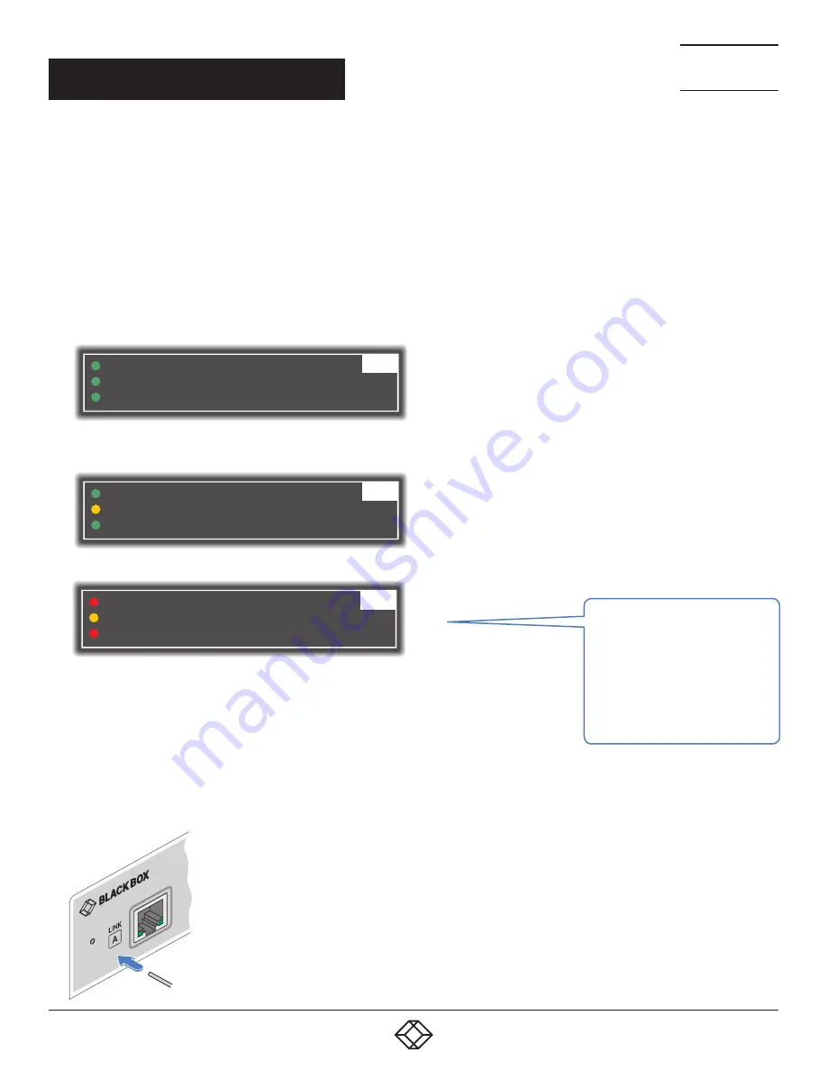
On the left side of the front panel of each module, you will find a small reset hole which is used to invoke special functions.
TO RESET A MODULE
1 Use a thin implement, such as a
straightened paperclip, to press and release
the button concealed behind the small hole.
The PWR indicator will show
red
.
After a few seconds, the indicator will
change from
red
to
green
to show that the
reset procedure is complete.
CHAPTER 4: CONFIGURATION


