Chapter 3: Configuration
Page 26
724-746-5500 | blackbox.com
LGC340A
TX1/2
Ingress Bandwidth
Limit
(CIR)
Monitors the traffic entering the unit (ingress),
discarding traffic that exceeds a fixed Committed
Information Rate (CIR) plus Burst Allocation (BA).
Frames are not held in queue, they either meet the
bandwidth limits and are accepted into the unit or
they are dropped.
Max Burst Allocation
size (BA)
The BA size is specified in bits; the # of bits above
the bandwidth limit before packets are thrown away.
Ingress Burst
Allocation
Bandwidth Limiting can be set at Ingress of each port
individually by setting the MAX BW Limit in bits/Sec.
and the BA in bits. Traffic in excess of the Bandwidth
limit plus BA for any time interval will be
dropped. This function utilizes an advanced “Leaky
Token-Bucket” algorithm to provide typical resolution
under 5% of the set values at all data rate and
frames sizes.
Egress Traffic
Shaping
Actively controls the transmitter and
hard
limits the
maximum frame rate that can be sent. Frames can
be delayed in the internal buffers of the unit, waiting
their turn to be sent. If the internal buffers are full,
excess traffic will be dropped. The Unit Rate Control
can be used to alleviate this.
Choose Layer 1, 2 or 3 for the counter, this will
determine how my bytes from the Ethernet frame are
to be included in the calculations.
Layer 1:
Layer 2:
Layer 3:
Pr DA to CRC + IFG
Frames DA to CRC
Frames DA to CRC – 18
(- 4 if frame is tagged)
OSI Level Used in
Calculations
(Open Systems
Interconnect, referring
to the seven layers
for TCP/IP)
Explanations:
Preamble
DA
CRC
IFG
= 8 bytes
= EtherNet Destination Address
= EtherNet Checksum
= 12 bytes
Unit Rate Control
Enable/Disable
Allows the end user to globally configure all
Bandwidth settings when enabling Unit Rate Control
(Flow Control). If the END device connected to the
port also has Flow Control enabled, this will ensure
packets will not be dropped.
Chapter 3: Configuration
LGC340A
724-746-5500 | blackbox.com
Page 31
NOTE
Selective Advertising must be used when connecting to a device that auto negotiates
and a specific speed and duplex mode is desired.
3.6 Configuration File Save/Restore Function
The Configuration File Save/Restore Function allows a user the ability to
backup all the configuration settings of a unit. With this backup, a user can
restore settings to a unit if necessary or use this backup to apply the same
settings to a different unit.
All configurable managed objects are saved in a configuration file that is stored
in the unit’s Large File Area. This includes all configurable settings such as
VLAN configurations, IP Address configuration and SNMP agent settings. The
configuration file can be transferred from the unit to a PC and saved to disk
through the iView
2
(iConfig view) protocol. The configuration file can be
transferred from a PC to a unit of the same type through iView
2
(iConfig view)
or TFTP into the unit’s Large File Area. After the transfer is complete, the unit
copies the configuration to flash and reboots.
The configuration file’s contents is device-type specific and can be identified by
iView
2
(iConfig view) as a configuration file as well as to what type of device it is
applicable to.
3.6.1 Saving a Configuration File to Disk:
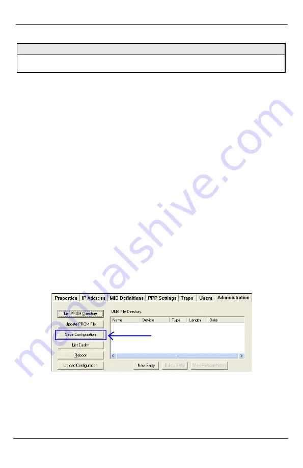
From the Administration Tab in iView
2
(iConfig view) click the
Save
Configuration
button:
The user is prompted for a filename:


