background image

15

CHAPTER 4: Installation

4. Gently insert the PCI Card into the slot. Make sure

that the adapter is seated properly.

5. Replace the screw.

6. Replace the cover.

7. Connect the power cord.

Installation is complete.

Summary of Contents for IC970C

Page 1: ...free in the U S Call 877 877 BBOX outside U S call 724 746 5500 FREE technical support 24 hours a day 7 days a week Call 724 746 5500 or fax 724 746 0746 Mailing address Black Box Corporation 1000 Pa...

Page 2: ...here is no guarantee that interference will not occur in a particular installation This equipment generates uses and can radiate radio frequency energy and if not installed and used in accordance with...

Page 3: ...eet FCC requirements shielded cables and power cords are required to connect this device to a personal computer or other Class B certified device This digital apparatus does not exceed the Class B lim...

Page 4: ...3 EU DECLARATION OF CONFORMITY EUROPEAN UNION DECLARATION OF CONFORMITY This equipment complies with the requirements of the European EMC Directive 89 336 EEC...

Page 5: ...a o lavabo s tano mojado o cerca de una alberca etc 6 El aparato el ctrico debe ser usado nicamente con carritos o pedestales que sean recomendados por el fabricante 7 El aparato el ctrico debe ser mo...

Page 6: ...contactos y recept culos donde salen del aparato 14 El equipo el ctrico debe ser limpiado nicamente de acuerdo a las recomendaciones del fabricante 15 En caso de existir una antena externa deber ser l...

Page 7: ...rks of International Business Machines Corporation Windows and Windows NT are either registered trademarks or trademarks of Microsoft Corporation in the United States and or other countries Any other...

Page 8: ...nical Description 11 2 4 RS 232 DB25 Male DTE Connector Pin Assignments 11 3 Card Setup 12 3 1 Address and IRQ Selection 12 3 2 Clock Modes 12 3 3 Baud Rates and Divisors for D1 Mode 13 4 Installation...

Page 9: ...ontents continued Chapter Page Appendix A Troubleshooting 16 A 1 Tips 16 A 2 Calling Black Box 17 A 3 Shipping and Packaging 18 Appendix B Electrical Interface 19 Appendix C Asynchronous Communication...

Page 10: ...re Tolerance Operating 32 to 122 F 0 to 50 C Storage 4 to 158 F 20 to 70 C Relative Humidity 10 to 90 noncondensing MTBF Greater than 150 000 hours calculated Power 5 VDC 480 mA Size 2 3 H x 4 9 W 5 8...

Page 11: ...up to 460 8 kbps 2 2 What the Package Includes The PCI Card is shipped with the following items 1 RS 232 Single Port PCI Card 1 Serial Utilities Software CD ROM containing drivers for Windows 3 1x 95...

Page 12: ...chip features programmable baud rates data format interrupt control and industry leading 128 byte FIFOs 2 4 RS 232 DB25 Male DTE Connector Pin Assignments Signal Name Pin Mode TD Transmit Data 2 Outpu...

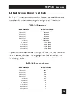
Page 13: ...I Card uses a unique clocking option that allows you to select from divide by 4 and divide by 1 clocking modes These modes are selected at Header J1 See Appendix D for proper location To select the ba...

Page 14: ...ps 4800 bps 1200 bps 9600 bps 2400 bps 19 2 kbps 4800 bps 57 6 kbps 14 4 kbps 115 2 kbps 28 8 kbps 230 4 kbps 57 6 kbps 460 8 kbps 115 2 kbps If your communications package allows the use of baud rate...

Page 15: ...R OPERATING SYSTEMS Refer to the appropriate section of the Serial Utilities Software 4 2 System Installation The RS 232 Single Port PCI Card can be installed in any of the PCI expansion slots and con...

Page 16: ...CHAPTER 4 Installation 4 Gently insert the PCI Card into the slot Make sure that the adapter is seated properly 5 Replace the screw 6 Replace the cover 7 Connect the power cord Installation is comple...

Page 17: ...se adapters as well as the IRQ if any 2 Configure your PCI Card so that there is no conflict with currently installed adapters No two adapters can occupy the same I O address 3 Make sure the PCI Card...

Page 18: ...in the SeaCOM folder on the Start Menu during the setup process First find the ports using the Device Manager then use WinSSD to verify that the ports are functional 7 Always use the diagnostic softwa...

Page 19: ...nvolved in the problem any particular application that when used appears to create the problem or make it worse A 3 Shipping and Packaging If you need to transport or ship your RS 232 Single Port PCI...

Page 20: ...n Data Terminal Equipment and Data Circuit Terminating Equipment Employing Serial Binary Data Interchange Both implementations are in widespread use and will be referred to as RS 232 in this document...

Page 21: ...al data communication for PC compatibles and PS 2 computers The original PC was equipped with a communication COM port that was designed around an 8250 Universal Asynchronous Receiver Transmitter UART...

Page 22: ...n Common methods are called E ven Parity or O dd Parity Sometimes parity is not used to detect errors on the data stream This is referred to as N o parity Because each bit in asynchronous communicatio...

Page 23: ...22 RS 232 SINGLE PORT PCI CARD transmitting and receiving ends The communication parameters are baud rate parity number of data bits per character and stop bits that is 9600 N 8 1...

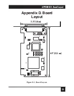
Page 24: ...23 APPENDIX D Board Layout Appendix D Board Layout Figure D 1 Board Layout 2 3 5 8 cm 4 9 12 5 cm...

Page 25: ...1000 Park Drive Lawrence PA 15055 1018 724 746 5500 Fax 724 746 0746 Copyright 2002 Black Box Corporation All rights reserved...

Reviews: