background image

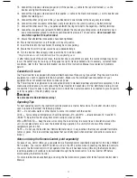
• Overload and over-temperature shutdown activated if AC output exceeds rated watts
• AC short-circuit shutdown
• Low voltage audible alarm (sounds at 10.5 volts input)
• Low-voltage shutdown (activates at 10.0 volts DC)
• High-input voltage shutdown (activates at above 15.5 volts DC)
MAXX SST™ uses a 12 volt DC power source like those found in motor vehicles, or it can be operated using
multiple battery configurations with commercial battery chargers or solar battery chargers. For most heavy-duty
applications, a multiple battery configuration and the use of deep-cycle batteries is required.
When using multiple batteries, inverters can be operated from one of the vehicle 12 volt batteries, so there’s
always one battery with adequate charge to start an engine.
MAXX SST™ includes a high-surge capability. This is required to start heavy loads, such as motors and other
inductive devices.

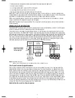
PRINCIPLE OF OPERATION

The MAXX SST™ inverter converts 12 volt DC (direct current) from a vehicle battery or other 12 volt DC power
source to standard 120 volt AC (alternating current) household power.
It converts power in two stages (see the diagram below). In the first stage, the inverter raises the 12 volt DC
input to 145 volts DC. This MAXX SST™ inverter uses high-frequency conversion techniques that replace bulky
and heavy transformers found in older inverters. In the second (output) stage, the inverter converts the 145 volt
DC to 110/120 volt AC using multiple banks of metal-oxide semiconductor field-effect transistors (MOSFETs).
The unit’s solid-state circuitry ensures excellent overload protection and the ability to operate reactive loads
such as those found in inductive motors. In this stage, the inverter functions as a high-power bipolar switch,
alternately applying opposite polarity to the AC outlet HOT and NEUTRAL terminals.

Notes:

Simplified diagram.

Cables, fuse and battery are not included and must be supplied by user.

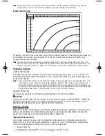
The Power Inverter Output Waveform

The AC output waveform of the Power Inverter is known as “modified sine wave.” It is a waveform that has
characteristics similar to the sine wave shape of utility power. This type of waveform is suitable for most AC
loads, including linear and switching power supplies used in electronic equipment, transformers, and motors.
The modified sine wave produced by the Power Inverter has an RMS (root mean square) voltage of 115 volts,
which is the same as standard household power. Most AC voltmeters (both digital and analog) are sensitive to
the average value of the waveform rather than the RMS value. They are calibrated for RMS voltage under the
assumption that the waveform measured will be a pure sine wave. These meters will not read the RMS voltage
of a modified sine wave correctly. They will read about 20 to 30 volts low when measuring the output of the
inverter. For accurate measurement of the output voltage of this unit, use a true RMS reading voltmeter such as
a Fluke 179, Fluke 79 III series, Beckman 4410 or Triplett 4200.

Modified Sine Wave and Sine Wave Comparison

12 VOLT DC

INPUT FROM

BATTERY

AWG

WIRE

AWG

WIRE

AWG

WIRE

+ –

+

ANL

FUSE

(external)

TERMINAL

BLOCK

DC TO DC

CONVERTER

INTERNAL WARNINGS &

PROTECTION CIRCUITS

VOLT, AMP METERS*

OVER TEMP &

VOLT INDICATORS

ON/OFF

SWITCH

145 VDC

MOSFET

BIPOLAR

SWITCH

BANKS

NEUTRAL

HOT

(2, 3 OR 4)

OUTLETS

GROUND

SENSE

FAULT

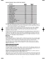
See the “Specifications”
section for wire gauges
and fuse amperages.

4

VEC054D_ManualEN_092107.qxp  9/24/2007  3:40 PM  Page 4

Summary of Contents for MAXX SST

Page 1: ...THIS PRODUCT FOR ANY REASON PLEASE CALL 1 800 544 6986 BEFORE YOU CALL HAVE THE CATALOG No AND DATE CODE AVAILABLE IN MOST CASES A BLACK DECKER REPRESENTATIVE CAN RESOLVE THE PROBLEM OVER THE PHONE IF YOU HAVE A SUGGESTION OR COMMENT GIVE US A CALL YOUR FEEDBACK IS VITAL TO BLACK DECKER SAVE THIS MANUAL FOR FUTURE REFERENCE Cat VEC054D September 2007 Copyright 2007 Black Decker Printed in China ...

Page 2: ...like AVOID UNINTENTIONAL STARTING Don t carry plugged in appliance with finger on switch Be sure switch is off when plugging in PROPER COOLING is essential when operating the inverter Do not place the unit near the vehicle s heat vent or in direct sunlight ELECTRICAL FAULT CIRCUIT INTERRUPTOR protection should be provided on the circuits or outlets to be used Receptacles are available having built...

Page 3: ...SHOCK Do not connect to AC distribution wiring Do not make any electrical connections or disconnections in areas designated as IGNITION PROTECTED This unit is NOT approved for ignition protected areas NEVER immerse the unit in water or any other liquid or use when wet Do not insert foreign objects into the AC outlet or the USB outlet WARNING TO REDUCE THE RISK OF FIRE Do not operate near flammable...

Page 4: ...form of 120 volt AC outlets to run most household or electronic appliances Before introduction of SST high start up currents from large inductive loads could shut down an inverter SST improves inverter operation by Gradual voltage ramp up during inverter start up eliminating failed cold starts under load Output that momentarily dips in voltage and quickly recovers to allow large motorized loads to...

Page 5: ... and the ability to operate reactive loads such as those found in inductive motors In this stage the inverter functions as a high power bipolar switch alternately applying opposite polarity to the AC outlet HOT and NEUTRAL terminals Notes Simplified diagram Cables fuse and battery are not included and must be supplied by user The Power Inverter Output Waveform The AC output waveform of the Power I...

Page 6: ...rted and resume normal operation Note To restart the inverter turn it off and then on again The on off Switch is located on the unit s Front Panel refer to the Control and Functions section of this Instruction Manual The inverter powers resistive loads the easiest however larger resistive loads such as electric stoves or heaters could draw more wattage than the inverter can deliver on a continuous...

Page 7: ...he battery or batteries is are fully charged If the connections are good and the battery is charged but the voltage still drops below 11 volts you may need to use a larger battery or battery combination CAUTION Rechargeable Devices Certain rechargeable devices do not operate well from a modified sine wave inverter They only operate properly from a standard household outlet which provides a pure si...

Page 8: ...ttery size you will need to operate appliances from MAXX SST inverters follow these steps 1 Determine the wattage of each appliance and or tool you will need to simultaneously operate from the inverter To do this read the labels on the equipment to be operated 2 Estimate the number of hours the equipment will be in use between battery recharges 3 Determine the total watt hours of energy use the to...

Page 9: ...DC the inverter will automatically shut down If the low voltage alarm sounds when the battery is fully charged refer to the Troubleshooting section of this Instruction Manual CIRCUIT PROTECTION The inverter has electronic circuit protection against overload or short circuit conditions CAUTION If turning the ON OFF Switch OFF then ON again does not reset the inverter DO NOT ATTEMPT TO OPEN THE INVE...

Page 10: ...16 Call Vector Technical Support toll free at 1 800 544 6986 with any questions Installation Procedures When wiring the inverter to a 12 volt DC power source ensure that polarity is correct Reversed polarity will blow a fuse and may cause permanent damage to the inverter Review diagrams on page 3 if necessary to identify the location of the DC terminals Note The manufacturer s warranty does NOT co...

Page 11: ...ve cables to the battery do not exceed six feet 5 Using an appropriate AWG cable see the diagram on page 7 reposition the inverter and fuse holder if necessary 6 After you have performed the above preliminary installation steps proceed with the actual inverter installation Contact the manufacturer for any further installation information or questions Note This procedure is for using locally purcha...

Page 12: ...pment does not exceed maximum continuous power The Power Inverter is engineered to be connected directly to standard electrical and electronic equipment in the manner described above Do not connect the Power Inverter to household or RV AC distribution wiring Do not connect the Power Inverter to any AC load circuit in which the neutral conductor is connected to ground earth or to the negative of th...

Page 13: ...adio Snow in picture Keep inverter and antenna distant from each interference buzzing sound other Use shielded antenna Connect antenna to amplifier Problem Solution Buzzing sound in audio systems Some inexpensive stereo systems and boom boxes emit a buzzing sound from their speakers when operated from the Power Inverter This occurs because the power supply in the electronic device does not adequat...

Page 14: ...l advice repair or genuine factory replacement parts contact the Black Decker location nearest you To find your local service location refer to the yellow page directory under Tools Electric or call 1 800 544 6986 or visit www blackanddecker com CAUTION If the cord becomes damaged return the entire unit to manufacturer immediately for service repair FULL TWO YEAR HOME USE WARRANTY Black Decker U S...

Page 15: ...y _ 82 No load current draw 1 0 amp Over voltage shutdown 15 5 0 5 volts DC Low voltage shutdown 10 0 0 3 volts DC Thermal shutdown auto reset Yes North American standard outlets 3 ANL fuse rating for direct hardwire 500 Proper cable gauge AWG 6 ft 1 0 Proper cable gauge AWG 10 ft 3 0 For lengths greater than 10 feet please call 1 800 544 6986 Imported by Black Decker U S Inc 701 E Joppa Rd Towson...

Reviews: