Ventless Hood System
Installation
5
Installation
Unpacking and Handling
Inspection for Shipping Damage
YOU
are responsible for filing all freight claims with the delivering truck line. Inspect all cartons and crates
for damage as soon as they arrive. If damage to cartons or pallets is found, or if a shortage is found, note
this on the bill of lading (all copies) prior to signing and receiving.
If damage is found when the equipment is opened, immediately call the delivering truck line and follow up
the call with a written report indicating concealed damage to your shipment. Ask for an immediate
inspection of your concealed damage item. Packaging material
MUST
be retained to show the inspector
from the shipping line.
Location and Clearance
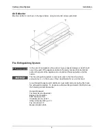
Place the Filter Hood in a location with clearance as shown below. These distances provide for proper
clearance to combustible surfaces, access for maintenance, and proper air flow from hood exit vent.
MINIMUM CLEARANCE HOOD TO
COMBUSTIBLE
18 in. (FH-28) SIDES, 0 in.
BACK, 0 in. TOP, 0 in. BOTTOM
APPLIANCE CLEARANCE
Cooking surface
must be at least 3.5 inches behind the front edge
of the hood.
Assembly and Mounting
Hood Mounting
1. Assemble the hood to the table using four 1/4” x 20 bolts (3/4” long) and lock washers. Mounting
brackets are fixed to the support legs as shown below.
Front Mounting Brackets
Rear Mounting Brackets
2. Seal the hood base to unit using NSF approved silicone rubber sealant.
Summary of Contents for FH-28CT COUNTERTOP
Page 1: ...CS TM 041 01 Revised 04 17 13 Ventless Hood System MODEL FH 28CT COUNTERTOP Service Manual ...
Page 11: ...Ventless Hood System Installation 9 Figure 1 ...
Page 12: ...Ventless Hood System Installation 10 Figure 2 ...
Page 13: ...Ventless Hood System Installation 11 Figure 3 Right Side Pull Station Mounting ...
Page 14: ...Ventless Hood System Installation 12 Figure 4 Left Side Pull Station Mounting ...
Page 15: ...Ventless Hood System Installation 13 Figure 5 Complete Pull Station Mounting ...
Page 24: ...Ventless Hood System Replacement Parts 22 Figure 7 Blower Motor Assembly ...
Page 26: ...Ventless Hood System Replacement Parts 24 Figure 8 Right Side Cabinet Assembly ...
Page 28: ...Ventless Hood System Wiring Diagrams 26 Wiring Diagrams ...


