Ventless Hood System
Installation
8
1. Mount the fire extinguisher control as follows:
a. When viewed from the front of the hood, mount the fire extinguisher control/cylinder plate to
right hand side of hood (see Figure 1) when hood is mounted on left end of table or to left
side of hood (see Figure 2) when hood is mounted on right end of table. Use (2) ¼-20x3/4”
bolts and lockwashers to secure plate to rear of hood frame.
b. Attach cylinder actuator and discharge fitting assembly cylinder.
c. Mount cylinder on bracket.
d. Attach 8” nipple, 17.5” nipple, 90° ells, and union/vent assembly as shown in Figure 1 or
Figure 2. It may be necessary to rotate the union and elbow 180° to attach to cylinder union.
e. Attach conduit lengths and corner pulleys to A+ control box as shown in Figure 1 or Figure 2
simultaneously routing cable per standard Range Guard
procedures.
f.
Route flexible conduit as shown to top of A+ control box.
g. Connect microswitch interlock to hood electrical wires per wiring diagram provided in this
manual. Refer to the electrical diagram included in this manual (see page 26).
2. Mount the Pull Station as follows:
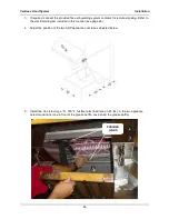
a. Remove protective plastic from all parts.
b. Mount remote pull box to remote pull enclosure bottom using (2) ¼-20x ¾ bolts,
lockwashers, and nuts.
c. Mount remote pull mounting plate to side of table using hardware provided with table.
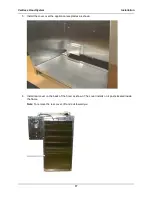
d. Refer to in Figure 3 or Figure 4. Attach remote pull enclosure bottom to inside of mounting
plate using (6) #10 sheetmetal screws.
e. Attach conduit lengths and corner pulleys to remote pull box as shown in Figure 3 or Figure 4
simultaneously routing cable per standard Range Guard
procedures.
f.
Attach remote pull enclosure top to mount plate and enclosure bottom using (8) #10
sheetmetal screws.
h. Mount remote pull cover plate. Refer to Figure 5 for complete pull station mounting.
Summary of Contents for FH-28CT COUNTERTOP
Page 1: ...CS TM 041 01 Revised 04 17 13 Ventless Hood System MODEL FH 28CT COUNTERTOP Service Manual ...
Page 11: ...Ventless Hood System Installation 9 Figure 1 ...
Page 12: ...Ventless Hood System Installation 10 Figure 2 ...
Page 13: ...Ventless Hood System Installation 11 Figure 3 Right Side Pull Station Mounting ...
Page 14: ...Ventless Hood System Installation 12 Figure 4 Left Side Pull Station Mounting ...
Page 15: ...Ventless Hood System Installation 13 Figure 5 Complete Pull Station Mounting ...
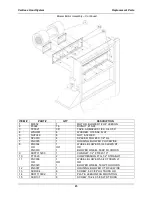
Page 24: ...Ventless Hood System Replacement Parts 22 Figure 7 Blower Motor Assembly ...
Page 26: ...Ventless Hood System Replacement Parts 24 Figure 8 Right Side Cabinet Assembly ...
Page 28: ...Ventless Hood System Wiring Diagrams 26 Wiring Diagrams ...


