background image


16

mode 

(VERT MODE 

set to 

DUAL), 

and with 

alternate sweep only 

(PULL CHOP 

not engaged). 

3.


In the 

EXT 

position, the signal applied to the 

EXT 

TRIG 

jack becomes the trigger source. This signal 

must have a timing relationship to the displayed 
wave-forms for a synchronized display. 

4.


In the 

LINE 

position of the 

COUPLING 

switch, 

triggering is derived from the input line voltage (5 
0/60 Hz) and the trigger 

SOURCE 

switch is disabled. 

This is useful for measurements that are related to 
line frequency. 

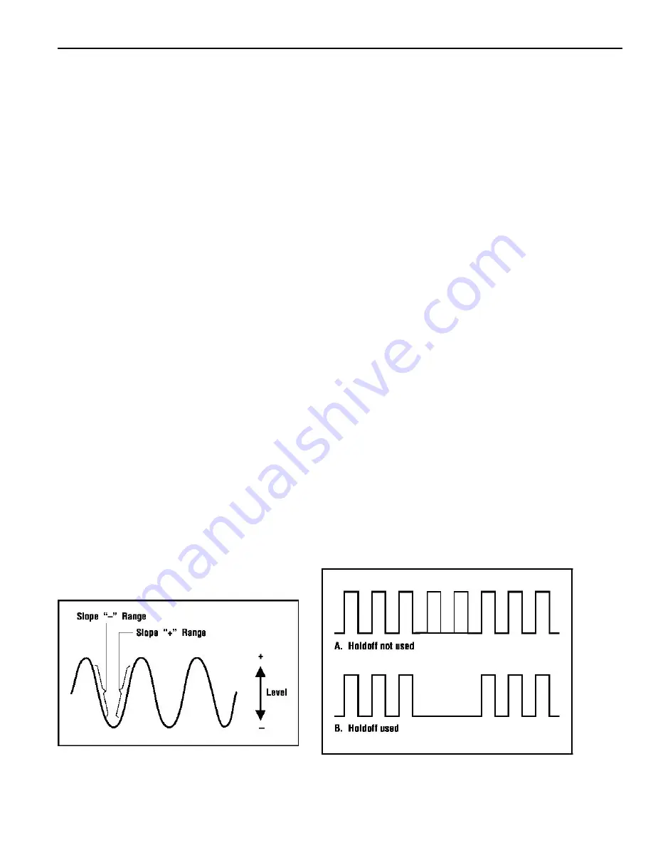
TRIG LEVEL/PULL (–) SLOPE Control 

(Refer to Fig. 3) 

A sweep trigger is developed when the trigger source 

signal crosses a preset threshold level. Rotation of the 

TRIG LEVEL 

control varies the threshold level. In the 

direction (clockwise), the triggering threshold shifts to a 
more positive value, and in the – direction 
(counterclockwise), the triggering threshold shifts to a 
more negative value. When the control is centered, the 
threshold level is set at the approximate average of the 
signal used as the triggering source. Proper adjustment of 
this control usually synchronizes the display. 

The 

TRIG LEVEL 

control adjusts the start of the sweep 

to almost any desired point on a waveform. On sine wave 
signals, the phase at which sweep begins is variable. 
Note that if the 

TRIG LEVEL 

control is rotated toward 

its extreme 

or – setting, no sweep will be developed in 

the normal trigger mode because the triggering threshold 
exceeds the peak amplitude of the sync signal. 

When the 

PULL (–) SLOPE 

control is set to the 

(“in”) 

position, the sweep is developed from the trigger 

source waveform as it crosses a threshold level in a 
positive-going direction. When the 

PULL (–) SLOPE 

control is set to the 
– (“out”) position, a sweep trigger is developed from the 
trigger source waveform as it crosses the threshold level in 
a negative-going direction. 

TIME BASE Control 

Set the 

Time Base TIME/DIV 

control to display the desired 

number of cycles of the waveform. If there are too many cycles 
displayed for good resolution, switch to a faster sweep time. If only a 
line is displayed, try a slower sweep time. When the sweep time is 
faster than the waveform being observed, only part of it will be 
displayed, which may appear as a straight line for a square wave or 
pulse waveform. 

HOLDOFF Control 

(Refer to Fig. 4) 

A “holdoff” period occurs immediately after the completion of 

each sweep, and is a period during which triggering of the next sweep 
is inhibited. The normal holdoff period varies with sweep rate, but is 
adequate to assure complete retrace and stabilization before the next 
sweep trigger is permitted. The 

HOLDOFF 

control allows this 

period to be extended by a variable amount if desired. 

This control is usually set to the 

MIN 

position (fully 

counterclockwise) because no additional holdoff period is necessary. 
The 

HOLDOFF 

control is useful when a complex series of pulses 

appear periodically such as in Fig. 4B. Improper sync may produce a 
double image as in Fig. 4A. Such a display could be synchronized 
with the 

VAR SWEEP 

control, but this is impractical because time 

measurements are then uncalibrated. An alternate method of 
synchronizing the display is with the 

HOLDOFF 

control. The 

sweep speed remains the same, but the triggering of the next sweep is 
“held off” for the duration selected by the 

HOLDOFF 

control. Turn 

the 

HOLDOFF 

control clock-wise from the 

MIN 

position until the 

sweep starts at the same point of the waveform each time. 


Fig. 3. Function of Slope and Level Controls. 

Fig. 4. Use of HOLDOFF Control. 


Summary of Contents for 2522C

Page 1: ...20 MHz DIGITAL STORAGE ANALOG OSCILLOSCOPE INSTRUCTION MANUAL Model 2522C...

Page 2: ...wet 4 Use the time proven one hand in the pocket technique while handling an instrument probe Be particularly careful to avoid contacting a nearby metal object that could provide a good ground return...

Page 3: ...AL STARTING PROCEDURE 14 SINGLE TRACE DISPLAY 14 DUAL TRACE DISPLAY 14 TRIGGERING 15 MAGNIFIED SWEEP OPERATION 17 X Y OPERATION 17 VIDEO SIGNAL OBSERVATION 17 DIGITAL STORAGE OPERATION 17 MAINTENANCE...

Page 4: ...r CRT with large 8 x 10 centimeter viewing area Convenience Trace rotation electrically adjustable from front panel 0 10 90 and 100 markers for rise time measurements DUAL TRACE FEATURES Dual Trace Mo...

Page 5: ...for observing composite video waveforms TV H position can also be used as low frequency reject and TV V position can be used as high frequency reject Variable Holdoff Trigger inhibit period after end...

Page 6: ...oximately 500 kHz Polarity Reversal CH 2 invert Maximum Input Voltage 400 V dc ac peak HORIZONTAL AMPLIFIER Input through channel 1 input X Y mode CH 1 X axis CH2 Y axis Sensitivity Same as vertical c...

Page 7: ...ce Equivalent Time Sampling Bandwidth 20 MHz for repetitive waveforms Dot Joining Linear interpolation between samples Digital Display Modes Roll Stored data and display updated continually Refresh St...

Page 8: ...er cord summed and displayed as a single signal If the Channel 2 POSition PULL INVert control is pulled out the input from channel 2 is subtracted 7 CAL Terminal Terminal provides 0 5 V p p 1 kHz nomi...

Page 9: ...tion Adjusts vertical position of channel 1 trace PULL CHOP When this switch is pulled out in the dual trace mode the channel 1 and channel 2 sweeps are chopped and displayed simultaneously normally u...

Page 10: ...less of the VERTical MODE switch setting ALTernate Selects alternate triggering used in dual trace 19 Time Base TIME DIV Control Provides step selec mode permits each waveform viewed to become its 20...

Page 11: ...N inum normal The holdoff period increases pro gressively with clockwise rotation TRIGger LEVEL Trigger level adjustment determines the point on the triggering waveform where the sweep is trig gered R...

Page 12: ...and SLOW X100 if engaged ROLL mode is applicable only at time base settings of 10 ms div to 0 5 S div 33 SINGLE Pushbutton Engaging this switch enables the single sweep mode of digital storage operati...

Page 13: ...o waveform should result EQUIPMENT PROTECTION PRECAUTIONS The following precautions will help avoid damage to the oscilloscope 1 Never allow a small spot of high brilliance to remain stationary on the...

Page 14: ...red POWER pushbutton 3 A trace should appear on the CRT Adjust the trace brightness with the INTENSITY control and the trace sharpness with the FOCUS control SINGLE TRACE DISPLAY Either channel 1 or c...

Page 15: ...y when first setting up the scope to observe a waveform it provides sweep for wave form observation until other controls can be properly set Once the controls are set operation is often switched back...

Page 16: ...SLOPE control is set to the out position a sweep trigger is developed from the trigger source waveform as it crosses the threshold level in a negative going direction TIME BASE Control Set the Time B...

Page 17: ...g fields of video and 5 ms div for complete frames two interlaced fields of video At most points of measurement a composite video signal is of the polarity that is the sync pulses are negative and the...

Page 18: ...ator goes out Single sweep mode can be used in the presence of very rapidly occurring events even continuous waveforms if desired In that case the period between pushing the RE SET switch and the arri...

Page 19: ...es 1000 ms 1 sec div when this switch is engaged This time base expansion is extremely useful for observing very slow events With it the scope is capable of recording an event up to 500 seconds in dur...

Page 20: ...e Pry fuseholder away from receptacle 3 When reinstalling fuseholder be sure that the fuse is installed so that the correct line voltage is selected see LINE VOLTAGE SELECTION LINE VOLTAGE SELECTION T...

Page 21: ...skills and test equipment required for instrument repair and calibration many customers prefer to rely upon B K Precision for this service To use this service even if the oscilloscope is no longer un...

Page 22: ...sured at the fastest sweep speed and using X10 magnification This sweep rate is 10 ns div A rise time of less than about five divisions at this sweep speed should be calculated Calculated Measurements...

Page 23: ...equency of the signal at the input jack As an example if three cycles are displayed the calculated frequency would be approximately 15 Hz This is obviously incorrect This occurs because the DSO is tak...

Page 24: ...Intentionally left blank...

Page 25: ...7 www bkprecision com 714 921 9095 Include with the returned instrument your complete return shipping address contact name phone number and description of problem LIMITED ONE YEAR WARRANTY B K Precisi...

Page 26: ...22820 Savi Ranch Parkway Yorba Linda CA 92887 www bkprecision com 2009 B K Precision Corp 481 315 9 001 Printed in Taiwan...

Reviews: