background image


Rev. 3.02 

- 21 -

SRP-350

3-5 Interface Specifications 

 
3-5-1 RS-232C Serial Interface 
 
3-5-1(a) Specification 

Item 

Description 

Remark 

Data Transmission 

• Serial 


Synchronization • 

Asynchronous 


HandShaking 
(Flow Control) 

• H/W : DTR / DSR 
• S/W : XON / XOFF 

XON: ASC Code 11h 
XOFF: ASC Code 13h

Signal Level 

• Logic”1” (MARK) : -3V ~ -15V 
• Logic”0” (SPACE) : +3V ~ +15V 


Baud Rate 

• 9600/19200/38400/57600 Bps 


Data Word Length 

• 7 Bit / 8 Bit 


Parity 

• None /    Even / Odd 


Connector 

• DB25P Female (I/F PBA) 


Table 3-14 RS-232C Specification 


 Note : The HandShaking (Flow Control) / Data Word Length / Baud Rate / Parity functions depend 

on the DIP Switch settings. Refer to the User’s Manual. 


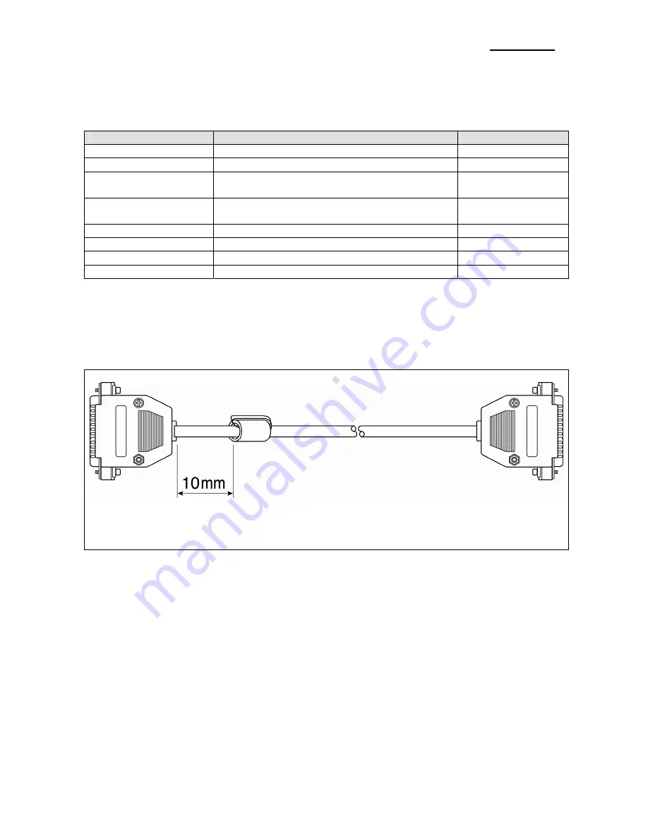
3-5-1(b) RS-232C I/F Cable 


Printer Side: D-SUB25P-Male 
 
Ferrite Core : 1 Turn (OP-118E : 18.2 x 12.5 x 25.5) 

CONN : User Spec 
In Case PC : D-SUB25P-Female or 

D-SUB9P-Female 

Figure 3-6 RS-232C Cable 

Summary of Contents for SRP-350 PlusA

Page 1: ...Service Manual SRP 350 Thermal Printer Rev 3 02 http www bixolon com ...

Page 2: ...self Test Mode 13 3 Product Specifications 15 3 1 Appearance 15 3 1 1 Printer Dimensions mm 15 3 1 2 AC Adapter Dimensions mm 15 3 1 3 Feature Locations 16 3 2 General Specifications 17 3 3 Thermal Printer Specifications 17 3 3 1 Printer Specification 17 3 3 2 Character Specification 18 3 3 3 Paper Specification 18 3 3 4 Reliability and Environment Specification 18 3 3 5 Printable Area 18 3 3 6 TP...

Page 3: ...mal Printer Head Circuit 38 5 Disassembly and Assembly 39 5 1 Case Lower block 39 5 2 Case Upper block 41 5 3 Frame block 44 6 Adjustments and Maintenance 47 6 1 Adjustment 47 6 1 1 Remaining Roll Paper Adjustment 47 6 1 2 Paper Jam 48 6 2 Maintenance 49 7 Troubleshooting 50 7 1 Power Problem 50 7 2 System Problem 51 7 3 Panel PBA and Sensor Problem 52 7 4 Thermal Printer Head and Feed Motor Probl...

Page 4: ...nic or machine readable from without prior written permission or BIXOLON Co Ltd Overview of this Receipt Printer This System Receipt Printer is a microprocessor based system using a 16 bit microprocessor This Service Manual provides the technical information for many individual component systems circuits and gives an analysis of the operations performed by the circuits If you need more technical i...

Page 5: ...Reverse the power plug prong in the AC outlet and repeat the test 5 Design Alteration Warning Never alter or add to the mechanical or electrical design of the Receipt Printer Unauthorized alterations might create a safety hazard Also any design changes or additions will void the manufacture s warranty 6 Components parts and wiring that appear to have overhead or that are otherwise damaged should b...

Page 6: ...ents Reinstall all such elements to their original position 3 After servicing always check that the screws components and wiring have been correctly reinstalled Make sure that the portion around the serviced part has not been damaged 4 Check the insulation between the blades of the AC plug and accessible conductive parts example metal panels and input terminals 5 Insulation Checking Procedure Disc...

Page 7: ...y to install it Most replacement ESDs are packaged with leads that are electrically shorted together by conductive foam aluminum foil or other conductive materials 8 Immediately before removing the protective material from the leads of a replacement ESD touch the protective material to the device will be installed 9 Minimize body motions when handling unpacked replacement ESDs Motions such as brus...

Page 8: ...ter 2 Plug RS 232 RS 485 USB or Parallel Cable connector into the I F connector on the printer 3 Tighten the screws on both sides of the connector 4 Turn on the printer host ECR and Computer 2 1 4 Paper Roll Installation Figure 2 3 Cash Drawer Cable Installation 1 Turn the printer off 2 Plug the Cash Drawer cable connector into the connector on the printer To remove the Cash Drawer cable press the...

Page 9: ...e the three screws from the bottom of the Case Lower Separate the Case Lower from the Main Body 3 Attach the Plate Spring to the right side of Frame Body and tighten a screw 4 Check whether it works properly by pressing the Push Button after tightening the screw 5 After assembling the Plate Spring the height will be 7 10 mm when pressing the Push Button If no problem Re assemble in the reverse ord...

Page 10: ...he BRKT Hanger to the Case Lower then tighten four screws 7 Attach the BRKT Mount to the wall firmly with the eight screws Be sure that the BRKT attached properly to match the direction of arrow And the BRKT Mount should be always fixed vertically 8 Insert the BRKT Hanger of Set to the BRKT Mount ...

Page 11: ...ffect and then on again Figure 2 5 Setting the DIP switches 2 2 2 Setting the DIP switch RS 232C Serial Interface DIP Switch 1 SW Function ON OFF Default 1 Auto Line Feed Always enabled Always disabled OFF 2 Reserved OFF 3 Handshaking XON OFF DTR DSR OFF 4 Word length 7 bits 8 bits OFF 5 Parity check Yes No OFF 6 Parity selection EVEN ODD OFF 7 ON 8 Baud rate selection Refer to the Following Table...

Page 12: ...Disable Enable OFF 4 Code Page Selection Refer to the Following Table 3 OFF 5 OFF 6 Select Print Density Refer to the Following Table 2 OFF 7 Near End Sensor Status Disable Enable OFF 8 Code Page Selection Refer to the Following Table 3 OFF Table 1 Baud rate bps Selection Transmission speed SW 7 SW 8 9600 baud ON OFF 19200 baud OFF OFF 38400 baud ON ON 57600 baud OFF ON Table 2 Print Density Selec...

Page 13: ... D 4 2 0 A 4 3 4 3 4 3 A B C C C Note A period is printed for each code that no ASCII equivalent Note During the hex dump all commands expect DLE EOT and DLE ENQ are disabled 5 When the printing finishes turn off the printer 6 Turn on the printer and then the hexadecimal model is off 2 2 5 The self Test Mode The self test checks whether the printer has any problem If the printer does not function ...

Page 14: ...Rev 3 02 14 SRP 350 A Serial Self Test Sheet B Parallel Self Test Sheet Figure 3 13 The Self Test Sheet ...

Page 15: ...Rev 3 02 15 SRP 350 3 Product Specifications 3 1 Appearance 3 1 1 Printer Dimensions mm Figure 3 1 Printer Dimension 3 1 2 AC Adapter Dimensions mm Figure 3 2 Adapter Dimension ...

Page 16: ...Rev 3 02 16 SRP 350 3 1 3 Feature Locations Figure 3 3 Feature Location ...

Page 17: ...Type BULK Speed 12 Mbps Full Speed Power Self Powered Printer Printing Method Thermal Line Printing Printing Speed 150 mm Sec 46 2 Line Sec Font A 1 6 Feed Auto Cutter Type Guillotine Cutting Method 1 Point Partial Cutting Power Consumption Approx 27W Peak AC Adapter Input AC 100V 240V 50Hz 60Hz Output DC 24V 5 2 5A Ripple and Noise 200mV Environment Condition Temperature 0 45 Humidity 30 80 RH We...

Page 18: ...aper can be used instead of the specified paper above TF50KS E Nippon Paper industries Co Ltd PD 160R New Oji Paper Mfg Co Ltd F380 Kansaki Specialty Paper Inc USA 3 3 4 Reliability and Environment Specification Item Description Remark Life Mechanism 15 Million lines Head 1x10⁸ Pulses 100Km Auto Cutter 1 500 000 Cut MCBF 37 000 000Lines Environmental Temperature Operating 0 C 45 C Storage 10 C 50 ...

Page 19: ... Thermister Temperature Number of Dots to be Energized simultaneously 256 Dots Note 1 Logic Supply Voltage Vdd 7 V Include Peak Voltage of Vdd Logic input Voltage Vin 0 5 Vdd 0 5 V Table 3 7 TPH Maximum Condition At 25 3 3 7 Other Component Specification Item Description Remark Auto Cutter Model ORC RUY80 OHYANE RIKI MFG Co Ltd Type Guillotine Type Motor DC Brush Motor FK 180SH 12280 Mabuchi Motor...

Page 20: ...0 75A When 230V In rush Current Max 30A Peak to Peak 115Vac 25 Line Regulation 24V 1 Load Regulation 24V 5 Ripple Noise Peak 200mV O C P Over Current Protect 3 0A 6 0A S C P Shot Current Protect Fold Back Method Table 3 12 Power Adapter SMPS Specification 3 4 2 SMPS Output Connector Pin Number Signal Name 1 24 VDC 2 GND 3 N C Shield Frame GND Table 3 13 Power Connector Pin Description Figure 3 5 P...

Page 21: ...V Logic 0 SPACE 3V 15V Baud Rate 9600 19200 38400 57600 Bps Data Word Length 7 Bit 8 Bit Parity None Even Odd Connector DB25P Female I F PBA Table 3 14 RS 232C Specification Note The HandShaking Flow Control Data Word Length Baud Rate Parity functions depend on the DIP Switch settings Refer to the User s Manual 3 5 1 b RS 232C I F Cable Printer Side D SUB25P Male Ferrite Core 1 Turn OP 118E 18 2 x...

Page 22: ... this signal 7 SG Signal Ground 20 DTR Output This signal indicates whether the printer is busy H W flow control 1 MARK Logic1 The printer is busy 2 SPACE Logic0 The printer is not busy 3 The host transmits a data to the printer after confirming this signal 4 When XON XOFF flow control is selected the host does not check this signal Table 3 15 RS 232C Pin Description 3 5 1 e H W Flow Control When ...

Page 23: ...n Manual about XON XOFF flow control 3 5 2 RS 485 Serial Interface 3 5 2 a Specification Item Description Remark Data Transmission Serial Synchronization Asynchronous HandShaking Flow Control H W DTR CTS Same as DSR S W XON XOFF XON ASC Code 11h XOFF ASC Code 13h Signal Level Logic 1 SD1 SD2 0 2V RD1 RD2 0 2V Logic 0 SD1 SD2 0 2V RD1 RD2 0 2V Baud Rate 9600 19200 38400 57600 Bps Data Word Length 7...

Page 24: ...r the host is BUSY or not If the host is BUSY the Printer does not transmit a data to the host If the host is not BUSY the Printer transmits a data to the Host The host is the same Refer to the Interface Part of Chapter 4 3 Special Circuit Diagrams 3 5 2 f S W Flow Control When XON XOFF flow control is selected the printer transmits XON ACSII 11h or XOFF ASCII 13h signal through the TXD line If th...

Page 25: ...ource Compatibility Mode Nibble Mode Byte Mode 1 Host nStrobe HostClk HostClk 2 Host Printer Data 0 LSB Data 0 LSB 3 Host Printer Data 1 Data 1 4 Host Printer Data 2 Data 2 5 Host Printer Data 3 Data 3 6 Host Printer Data 4 Data 4 7 Host Printer Data 5 Data 5 8 Host Printer Data 6 Data 6 9 Host Printer Data 7 MSB Data 7 MSB 10 Printer nAck PtrClk PtrClk 11 Printer Busy PtrBusy Data3 7 PtrBusy 12 P...

Page 26: ...0 mV Differential common Mode Range 0 8 2 5 V Single End Receiver Threshold 0 8 2 0 V Speed 12 Mbps Power Self Powered Cable Connector Cable 5m 2m Connector B Type Other Support USB SPEC V1 1 Table 3 20 USB Specification 3 5 4 b Signal Description Pin No Signal Name Assignment Color Function Shell Shield Drain Wire Frame Ground 1 VBUS Red Host Power DC5 V 500 mA 2 D White Differential Data Line 3 ...

Page 27: ...5 x 25 5 Figure 3 12 Drawer Cable 3 6 2 Cable Connection Pin No Description Direction 1 Frame GND 2 Cash Drawer Driver Signal 1 Output 3 Drawer Open Close Signal Input 4 24V 5 Cash Drawer Driver Signal 2 Output 6 Signal GND Table 3 23 Drawer Cable Connection Note 24V is always output through pin 4 during power on ...

Page 28: ...Rev 3 02 28 SRP 350 4 Hardware 4 1 Wiring Diagram Figure 4 1 Board Wiring Diagram ...

Page 29: ...Rev 3 02 29 SRP 350 4 2 Block Diagram Figure 4 2 Block Diagram ...

Page 30: ...oid Driving voltage Step motor driving voltage and a source voltage of the other voltage sources 2 Logic IC Driving Voltage 5V 5Vdc Logic driving voltage is produced by the step down Switching Regulator U1 LM2576 ADJ This is U1 produces rectangular ware This makes D4 B240 and L1 store energy The voltage is smoothed by CL2 470uF and then 5Vdc Logic voltage is produced 3 TPH Driving Voltage 24Vdc Q2...

Page 31: ... in order to start up CPU under Power on Reset circuit uses a reset ASM811JEUSF T U5 When 5Vdc is fallen under 4 0Vdc by Power off reset signal prohibits the system from miss operating by lowering down to 0V Figure 4 4 Reset Block Diagram Figure 4 5 Reset Waveform ...

Page 32: ...ircuit The circuit is used for opening cash drawer and driven by the Q4 Q5 2SD2170 When its state is high level signal Q4 or Q5 2SD2170 drive the solenoid to open the cash drawer As an optional item we provide sensor switch we call it a compulsory switch which checks the drawer whether it is opened or not This sensor switch turns on for the drawer open condition and turns off for the other Caution...

Page 33: ...CPU specify the I O port properly The following is the method of I F PBA detection First the CPU sends a I F Sel signal P7 0 to I F PBA The I F PBA has the three return Signal DIP 1 3 The CPU recognize the I F PBA by the value of the three return signal I F PBA DIP_C1 DIP_C2 DIP_C3 RS 232C L L H RS 485 L H L IEEE1284 H L L USB2 0 H H L No Connection L L L ...

Page 34: ...cation Block Diagram The CPU is used for serial communication And also RS 232C Driver MAX232 is used to serial communication Show following block diagram Figure 4 8 RS 232C Communication Block Diagram Figure 4 9 RS 232C Communication Waveform ...

Page 35: ...cation Block Diagram The CPU is used for serial communication And also RS 485 Driver MAX488 is used to serial communication Show following block diagram Figure 4 10 RS 485 Communication Block Diagram Figure 4 11 RS 485 Communication Waveform ...

Page 36: ...ith Centronics Nibble Byte Mode The Centronics is Forward and the Nibble Byte are reverse Mode Figure 4 10 IEEE1284 Communication Block Diagram 4 3 8 USB Communication Block Diagram The printer support the USB Universal Serial Bus The transfer type of the printer is the BULK Figure 4 11 USB2 0 Communication Block Diagram ...

Page 37: ...f 4 line The CPU sends repeatedly and continuously the scan data R1 R4 through The DIP S W information input in the return signal if the specific DIP S W is ON status during the given time The CPU reads the data through C1 C4 and analyzes what DIP S W is ON and performs the selected function Figure 4 12 DIP Switch Block Diagram ...

Page 38: ...stored in both Shift Register 1 and 2 Second the CPU send a Latch Signal to the Thermal Printer Then the Data of both Shift Register 1 and 2 256 2 512 Bits are moved to the Latch Register After that the CPU sends a Strobe Signal to the Thermal Printer Then the Printer outputs the Serial Data Each Strobe Signal manages the Printer Dot STB No DOT No DOTs STB SRP 350 Strobe Processing STB1 1 256 256 ...

Page 39: ...RP 350 5 Disassembly and Assembly 5 1 Case Lower block 1 Remove the three screws 2 Separate the Bracket Dip switch Case Lower Foot Rubber from the Printer 1 Remove the connector wires from main PBA and sub Assembly ...

Page 40: ...BA 2 Separate the BRKT Interface 3 Remove the two screws 4 Separate the BRKT Interface from the I F PBA Assembly 5 Separate the I F PBA from the Main PBA 6 Remove the four screws 7 Separate the Main PBA form the BRKT PCB 1 Separate the Cover Cable from Case Lower ...

Page 41: ...n 2 Remove the four screws 3 Separate the Cover Open 4 Separate the Cover Cutter 5 Remove the screws 1 Remove the two screws 2 Lift the Case Upper in the direction of an arrow during pushing the Push Button 3 Remove the three screws 4 Separate the Manual Cutter from the Case Upper ...

Page 42: ...emove the E Ring 2 Separate the Spring Tension the Shaft Hinge and the E Ring 3 Remove the E Ring 4 Separate the Bushing and the Roller Platen Assembly 1 Remove the Spring Hook 2 Remove the two screws 3 Separate the BRKT Hook ...

Page 43: ... 1 Remove the three screws 2 Separate the Fixed Cutter from the Cover Housing 3 Remove the two screws 4 Separate the Cutter Blade from Fixed Cutter 5 Remove the two screws 6 Separate the Cover Plate from the Cover Housing ...

Page 44: ...k 1 Pull out the Knob Cutter and separate it 2 Remove the two screws 3 Separate the BRKT Cover Cutter and the Auto Cutter from the Frame Main 1 Remove the screws 2 Push the Heat Sink Assembly in the direction of an arrow and separate it ...

Page 45: ...Plate ground and BRKT TPH Rear 3 Remove the two screws 4 Separate the Heat Sink and the Spring TPH 5 Separate the Connector from the Heat Sink 1 Remove the two screws 2 Separate the Frame Main from the BRKT PCB 3 Separate the Power Switch from the BRKT PCB ...

Page 46: ...mbly is separated Internal Spring Release Guide Button 7 Remove the screw And separate the Cover Sense PCB from the Frame Main 8 Remove the screw And separate the Plate Spring from the Frame Main 1 Remove the screw in the Frame Main 3PCS 2 Separate the Knob paper End 3 Separate the Housing paper End 2PCS 4 Separate the Sub Board 2PCS 5 Remove the Washer slip And Separate the Gear Idle from the Fra...

Page 47: ...cribed below Note The factory setting is based on a paper roll core with an outside diameter of 18mm If you use a paper roll with a core with an outside diameter of more than 18mm it is better to change to the upper position Rotate the tab at front side as described below 1 Open the paper roll cover 2 Rotate the tab at front or rear Position Note For your reference this shows the diameter at which...

Page 48: ... be opened open the cover open and remove the paper If the cover open can not be opened follow the below 1 Open the auto cutter cover with power ON 2 Then turn the knob clockwise with a coin or similar tool until the buzzer beep stops 3 Close the auto cutter cover 4 Pull up the roll paper cover by hand ...

Page 49: ...rn injury Be sure to wait for about 10 minutes after turning printer power off before beginning the cleaning 1 Open the cover open 2 Clean the thermal element the area that looks like it is marked a thin black line of the thermal head with a cotton swab moistened with an alcohol solvent ethanol methanol or IPA 3 After confirming that the alcohol solvent has been dried up completely close the cover...

Page 50: ...Rev 3 02 50 SRP 350 7 Troubleshooting This chapter describes the methods for troubleshooting in this Receipt Printer 7 1 Power Problem ...

Page 51: ...Rev 3 02 51 SRP 350 7 2 System Problem ...

Page 52: ...Rev 3 02 52 SRP 350 7 3 Panel PBA and Sensor Problem ...

Page 53: ...Rev 3 02 53 SRP 350 7 4 Thermal Printer Head and Feed Motor Problem ...

Page 54: ...Rev 3 02 54 SRP 350 7 5 Auto Cutter and Drawer Problem ...

Page 55: ...Rev 3 02 55 SRP 350 7 6 Dip S W and I F PBA Select Problem ...

Page 56: ...Rev 3 02 56 SRP 350 7 7 RS 232C Serial Communication Problem ...

Page 57: ...Rev 3 02 57 SRP 350 7 8 RS 485 Serial Communication Problem ...

Page 58: ...Rev 3 02 58 SRP 350 7 9 IEEE 1284 Parallel Communication Problem ...

Page 59: ...Rev 3 02 59 SRP 350 7 10 USB Communication Problem ...

Reviews: