Rev. 3.02
- 41 -
SRP-350
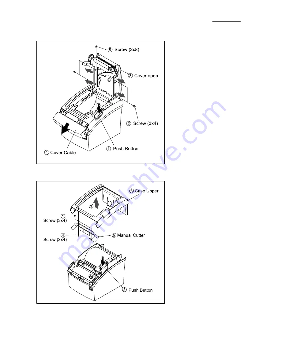
5-2 Case Upper block
1. Push the Button to open the Cove-
Open.
2. Remove the four screws.
3. Separate the Cover-Open.
4. Separate the Cover-Cutter.
5. Remove the screws.
1. Remove the two screws.
2. Lift the Case-Upper in the direction of
an arrow during pushing the Push-
Button.
3. Remove the three screws.
4. Separate the Manual-Cutter from the
Case-Upper.
Summary of Contents for SRP-350 PlusA
Page 1: ...Service Manual SRP 350 Thermal Printer Rev 3 02 http www bixolon com ...
Page 16: ...Rev 3 02 16 SRP 350 3 1 3 Feature Locations Figure 3 3 Feature Location ...
Page 28: ...Rev 3 02 28 SRP 350 4 Hardware 4 1 Wiring Diagram Figure 4 1 Board Wiring Diagram ...
Page 29: ...Rev 3 02 29 SRP 350 4 2 Block Diagram Figure 4 2 Block Diagram ...
Page 51: ...Rev 3 02 51 SRP 350 7 2 System Problem ...
Page 52: ...Rev 3 02 52 SRP 350 7 3 Panel PBA and Sensor Problem ...
Page 53: ...Rev 3 02 53 SRP 350 7 4 Thermal Printer Head and Feed Motor Problem ...
Page 54: ...Rev 3 02 54 SRP 350 7 5 Auto Cutter and Drawer Problem ...
Page 55: ...Rev 3 02 55 SRP 350 7 6 Dip S W and I F PBA Select Problem ...
Page 56: ...Rev 3 02 56 SRP 350 7 7 RS 232C Serial Communication Problem ...
Page 57: ...Rev 3 02 57 SRP 350 7 8 RS 485 Serial Communication Problem ...
Page 58: ...Rev 3 02 58 SRP 350 7 9 IEEE 1284 Parallel Communication Problem ...
Page 59: ...Rev 3 02 59 SRP 350 7 10 USB Communication Problem ...


