Roland CAMM-1 PNC-950, User Manual
The Roland CAMM-1 PNC-950 is an advanced cutting machine. Unlock the full potential of this product by downloading the comprehensive User Manual, available for free download from our website. Learn how to operate effortlessly and optimize your cutting tasks with this essential manual.
Share
Download


Reviews:
No comments
Related manuals for CAMM-1 PNC-950

C5800
Brand: Oki Pages: 6

C7300
Brand: Oki Pages: 44

C7500
Brand: Oki Pages: 13

C7300
Brand: Oki Pages: 20

C7300
Brand: Oki Pages: 2

C5300
Brand: Oki Pages: 28

Pico
Brand: B3 innovations Pages: 12

B410D
Brand: Oki Pages: 4

CLX-9350ND
Brand: Samsung Pages: 549

Aficio MP C6503SP
Brand: Ricoh Pages: 264

464de - X B/W Laser
Brand: Lexmark Pages: 27

ECOSYS M8124cidn
Brand: Kyocera Pages: 44

ESP 3200 Series
Brand: Kodak Pages: 90

DPU-30
Brand: SII Pages: 85

D30+
Brand: Rapid Shape Pages: 44
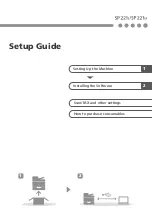
SP 221S
Brand: Linux Pages: 8

B4400L
Brand: Oki Pages: 105

C110 Series
Brand: Epson Stylus Pages: 4


