


ends of female connector and stripping cable, the signal of console cable is defined as
below,
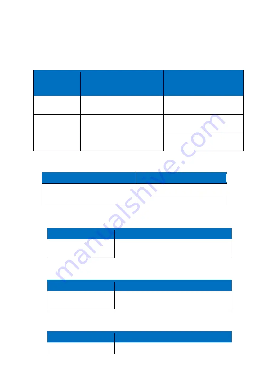
RS232 Cable(with DB9 female connector and stripping cable)
Color of cable
Corresponding DB9-Female Pin No.
Corresponding Pin No. of Router
(Pin 1 closes to power jack, Pin 5
closes to ethernet port)
Blue
2
(
RX
)
1(TX)
Brown
3
(
TX
)
2(RX)
Black
5
(
GND
)
3(GND)
RS485 Cable (RS485_1, RS485_2)
Relay Interface (Relay1, Relay2)
Relay Feature
Control the external switch
load capacity
Maximun Voltage switch: 30VDC/220VAC
Maximun Current switch: 5A
DI Interface (DI1, DI2)
DI Feature
Detect the slave device status
Input Range
Logic 0: wet contact 0-3VDC, or dry contact close.
Logic 1: wet contact 5-30VDC, or dry contact open.
ADC Interface (ADC1, ADC2)
ADC Feature
acquire the slave device analog input
Input Range
4~20mA Current input, or 0-5V Voltage input.
Color of cable
TG452 Router
Red
4(A)
Black
5(B)
Summary of Contents for TG452 Series
Page 1: ... Industrial Cellular Edge Gateway TG452 Series User Guide ...
Page 13: ...3 1 2 Network Display WAN LAN WiFi DHCP network information ...
Page 14: ...3 1 3 Routing Tables Display routing tables 3 1 4 System Log Display system log ...
Page 39: ...2 DI ports setting ...
Page 40: ...3 Relay Setting ...


