CB-100-1
22
F3
L1
L2
L3
PE
L1
L2
L3
B2
S2
S1
01
S3
H1
H2
K11
Y2
F5
P>
F6
P<
K10 15
N
L
11
12
14
SE-B1
B1
B2
1
2
6
PE
g
rau
g
re
y/g
ris
br
aun
bro
wn
marron
violett
violet
violet
rosa
pink
rosé
b
lau
b
lue
b
leu
K10 15
*Individueller Anschluss je nach ge
wählter Motor
var
iante und A
uslegung.
*Individual connection depending on chosen motor v
ersion and design.
Details zum Anschluss siehe Innenseite des
V
erdichter-Anschlusskastens
.
Details concer
ning connections see inside the ter
minal bo
xof the compressor
.
R8
K10 15
Option
X12
1
2
3
4
5
6
X13
Delta-PII /
OLC-K1
or
ange
DI4
DI5/DO3
DI6 (IMB)
DO3 (FsC2)
P24V Output
0V
0V
DI1 (Start)
DI2 (Force)
DI3 (pe/po1->2)
P24V Input
0V Input
V
ARIP
A
CK
(N1)
X11
X10
AI1
AI2
AO1
AO2
P10V
N10V
Input A
0V
Input B
0V
Status A
Status B
Analog I/O
REF
Saf
ety circuit:
ST
O
U
(M1)
V
(M2)
W
(M3)
Dig.
Inputs
Output
Dig.
Inputs
Input
PW Y
∆
3
4
5
R7
(Option)
M1*
X14
2
1
DO2B
DO2A
DO1B
DO1A
RDY
2
1
VsC1
4 ..20 mA
0 ..10
V
4
3
2
1
8
7
6
5
13
12
11
10
9
14
15
16
17
18
19
F1
Q1
1 0
20
K11 19
1
2
3
4
5
6
1
2
3
4
5
6
1
2
3
4
5
6
B1
F17
230V
T1
PE
L1
L3
H6
K10
20,21
22
R1..6
21
22
F2
N
L2
F12
K11 19
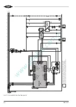
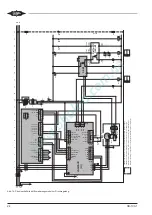
Abb. 13: Prinzipschaltbild ohne Erweiterungsmodul
Summary of Contents for VARIPACK FDU+12
Page 12: ...CB 100 1 12 1 2 3 4 Abb 7 Steuremodul abmontieren...
Page 46: ...CB 100 1 46 1 2 3 4 Fig 7 Dismounting the control module...
Page 70: ...Notes...
Page 71: ...Notes...


