background image

14

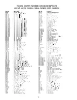
Item No.

Description

A16112

Head door latch assembly

HHS058S

Hex head screw,

5

16

-18

´

7

8

, SS

HHS060S

Hex head screw,

5

16

-18

´

1, SS

LW15S

Lock washer,

5

16

, SS

SSS15

Set screw,

5

16

-18

´

5

16

, SS

112-212

Waved washer

14TH

Head door hinge welded

14TP

Head door hinge pin, 1

1

2

"

14TP-1

Head door hinge pin, 1

1

4

"

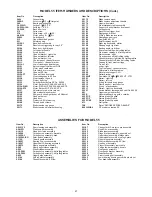
Item No.

Description

55135

Right support angle

55136

Left support angle

55138

Hinge bracket, upper wheel

55153

Head assembly, weldment, SS

55154

Head door, SS

55191

Head & door assembly, SS

55193

Hinge bracket assembly, upper wheel

55233

Head door assembly, SS

w/VTS7181

Summary of Contents for 55

Page 1: ... IMPORTANT NOTICE This Manual contains important safety instructions which must be strictly followed when using this equipment PTCT Mod 55 284 9 13 8 ...

Page 2: ...9 LUBRICATION 10 CHANGING THE SAW BLADE 10 WARNING LABEL LOCATIONS ON MACHINE 11 PARTS DIAGRAMS 12 OPERATOR S NOTES 17 WIRING DIAGRAM 23 OPTIONAL DOUBLE ROLLING TABLES PARTS LIST DIAGRAMS 24 OPTIONAL FIXED FRONT TABLE PARTS LIST DIAGRAMS 25 PARTS LIST ORDERING 26 PARTS ASSEMBLIES LIST ORDERING 27 WEARABLE SAW PARTS 28 OPERATOR S SIGNATURE PAGE 29 LIMITED WARRANTY 30 ...

Page 3: ...DE No one under eighteen 18 years of age should operate this equipment If you are uncertain about a particular task ask your supervisor This Manual contains a number of safe practices in the SAFETY TIP section Additional warn ings are placed throughout the Manual Warnings related to your personal safety are indicated by Warnings related to possible damage are indicated by BIRO also has provided a ...

Page 4: ... any Way From its Original Form This Machine in its Original Form Meets the Intent of O S H A Applicable Standards NEVER Operate With Saw Guide Bar with Saw Guard in the Raised Position or the Saw Guard Removed from the Saw Guide Bar ALWAYS Adjust Saw Guide Bar with Saw Guard to Within 1 2 of Product to be Cut ALWAYS Use Safety End Cut Pusher Plate for Smaller Products or The Last Cuts of Product ...

Page 5: ...3 ...

Page 6: ...ARABLE DAMAGE TO THE CONTACTOR G The BIRO Manufacturing Company is not responsible for permanent wiring connection or installation 5 Be sure saw blade is properly installed on the saw wheels and set at proper tension Turn the blade tensioning handle clockwise until the tension mark is even with the bottom of the upper wheel hinge plate as shown 6 Make sure the saw guide bar is in its lowest positi...

Page 7: ...WARNING LABELS FOR BIRO POWER SAWS SEE PAGE 11 FOR LOCATIONS ON MACHINE 5 ...

Page 8: ...osition or the Saw Guard Removed from the Saw Guide Bar ALWAYS Adjust Saw Guide Bar with Saw Guard to Within 1 2 of Product to be Cut ALWAYS Use Safety End Cut Pusher Plate for Smaller Products or The Last Cuts of Product DO NOT Use This Machine for Non Food Products DO NOT Use This Machine to Cut Pigs Feet DO NOT Wear Gloves While Operating ALWAYS Turn Off Unplug From Power Source and Perform Loc...

Page 9: ...face flush against meat gauge plate Move the meat carriage from right to left at a steady rate until fully past the saw blade Use left hand to remove and stack cut product NEVER REACH IN FRONT OF BAND TYPE SAW BLADE On the return stroke pull the product toward you away from saw blade 6 ALWAYS use the Safety End Cut Pusher Plate Part No 256P for smaller products or the last cuts of product The push...

Page 10: ...Standards ONLY Use Recommended Cleaning Equipment Materials and Procedures NEVER Spray Water or Other Liquid Substances Directly at Motor Power Switch or any Other Electrical Components ALWAYS Thoroughly Clean Equipment Daily CLEANING THE BIRO POWER CUTTER Disconnect the electrical power from the machine before cleaning Parts to be removed have been made accessible and can be removed without tools...

Page 11: ...s cleaned at least daily to ensure that it is in good condition and has not been damaged or tampered with a SAW WHEELS Clean outer diameter grooves daily Check for cracks gouges or wear on flange and grooves DO NOT IMMERSE UPPER WHEEL ASSEMBLY IN WATER b WHEEL CLEANER ASSEMBLIES Check condition of fiber cleaner change every four 4 weeks c REMOVABLE FINGER LIFT ASSEMBLY Check condition of saw guard...

Page 12: ...free movement of meat gauge arm on gear rack Gear rack to be kept lubricated at all times with light food grade oil Check operation of release handle Check that worm gear engages properly with gear rack h MEAT CARRIAGE ASSEMBLY Check free movement through full range of travel Check for side to side tolerance adjust as necessary Check condition of and grease bearings replace as necessary Check cond...

Page 13: ...ise Lift nylon filler Remove blade Install new blade by reversing procedure Be sure tension mark is even with the bottom of the hinge plate for proper blade tension WARNING LABELS LOCATIONS ON MODEL 55 POWER SAWS Item No 653PC E Warning label English 1 ea attached to head below Model S N plate 11 Item No 653PC E Warning label English 1 ea attached to channel bracket Item No 653PC SP Warning label ...

Page 14: ......

Page 15: ...13 ...

Page 16: ... 5 16 SS 112 212 Waved washer 14TH Head door hinge welded 14TP Head door hinge pin 11 2 14TP 1 Head door hinge pin 11 4 Item No Description 55135 Right support angle 55136 Left support angle 55138 Hinge bracket upper wheel 55153 Head assembly weldment SS 55154 Head door SS 55191 Head door assembly SS 55193 Hinge bracket assembly upper wheel 55233 Head door assembly SS w VTS7181 ...

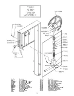
Page 17: ...rew SS 193 Saw guide bar spring 194KS 1 Lock knob 11 8 196 Saw tension spring 360A1 Grease fitting Item No Description 55170 Blade tension cap gauge 55171 1 Blade tension adjustment housing 55172 Blade tension screw 55173 Blade tension adjustment handle 55174 Upper wheel hinge plate 55184 O ring blade tension screw 55192 Blade tension assembly 55194 Upper wheel assembly w hinge plate 55312 O ring ...

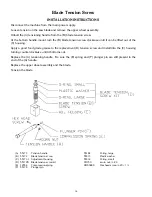
Page 18: ...ease to the replacement D tension screw and install into the C housing turning counterclockwise until it bottoms out Replace the A tensioning handle Be sure the E spring and F plunger pin are still present in the end of the A handle Replace the upper wheel assembly and the blade Tension the blade 16 A 55173 Tension handle B 55172 Blade tension screw C 55171 1 Adjustment housing D 55172K Blade tens...

Page 19: ... NOTES 17 ...

Page 20: ... A18247 Upper shaft brg assembly w o wheel A295 Wheel cleanqer assembly HHS005S Hex head screw 8 32 1 2 SS HHS010S Hex head screw 10 32 3 8 SS HN05S Hex nut 8 32 SS HN40S Hex nut 1 2 13 light jam SS S18253 Upper wheel aligning screw SS S229 Wheel cleaner arm spring SS S244 Wheel cleaner arm stud SS S295 Wheel cleaner arm SS S325 Wheel cleaner washer SS Item No Description 179 Wheel cleaner 18230DL...

Page 21: ......

Page 22: ...ew 8 32 1 2 SS HHS009S Hex head screw 10 24 SS HHS055S Hex head screw 5 16 18 3 4 SS HN05S Hex nut 8 32 SS LW15S Lock washer 5 16 SS S229 Wheel cleaner arm spring SS S235 Taper pin 4 3 4 SS S244 Wheel cleaner arm shoulder bolt SS S295 Wheel cleaner arm SS S325 Wheel cleaner arm washer SS S608 Back up guide carbide 131 Saw cleaner SS 14640 Wheel cleaner Rulon 179 Wheel cleaner 211Q Fastener knob 5 ...

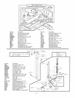
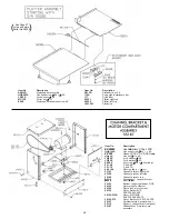
Page 23: ...washer 311 Rubber bumper for stops 311 1 Rubber bumper for movable stop 376 Drive screw 10 1 2 SS 55126 Channel EZ flow 55186 Channel assembly EZ flow Item No Description A175S Thumb guard assembly NSS AN15S Acorn nut 1 4 20 SS FW05S Flat washer 1 4 SS HN25S Hex nut 3 8 16 SS LW20S Lock washer 3 8 SS S155EZ 1 Weld stud 1 4 20 3 8 SS S155EZ 2 Weld stud 3 8 16 1 2 SS S155EZ 3 Hex stand off S155 11 M...

Page 24: ...ort channel brkt front panel 55187 Channel brkt motor comp assembly Item No Description AS415D Stationary bar assembly HHS025S Hex head screw 1 4 20 1 2 SS LW10S Lock washer 1 4 SS MC 10E Cotter key 1 8 1 S268 Stationary bar headless screw SS Item No Description S415D Stationary bar SS 119A Saw guide in stationary bar 177 Nylon filler 55291 Platter right top 55309 Platter left top 18212W Platter r...

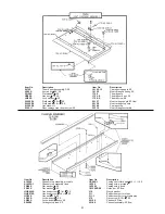
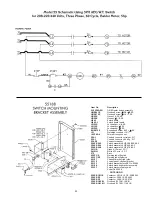
Page 25: ...eg WT 226 28 Connector washer 226EE 540 Switch assembly 5HP 208 220 60 3 226EE 544 Switch assembly 5HP 440 60 3 226EE 548 Switch assembly 5HP 575 60 3 241GR Green 12 wire 33 241WH White 12 wire 33 375 Rivet 653PC E Warning label English 653PC SP Warning label Spanish 55107 Channel bracket right side 55110 Control panel channel bracket 55133 Switch bracket before SR No 55059 55188 Switch mounting b...

Page 26: ...Wing nut 7 16 14 SS ...

Page 27: ......

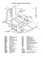
Page 28: ...Taper pin 6 3 4 SS VT460S Model S N plate 112 212 Waved washer 116RS Saw guide bar spacer block 119A Saw guide in stationary bar 131 Saw cleaner SS 14TH Head door hinge welded 14TP Head door hinge pin long Item No Description 14TP 1 Head door hinge pin short 14640 Wheel cleaner rulon 151 WT conduit 16015 3 Motor base plate wing nut 16155 13 Carriage stop angle SS 16159 Meat carriage bearing SS 162...

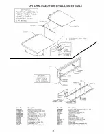
Page 29: ...it weldment 55121 Bottom support weldment DNS 55123 Motor mount weldment 55125 Pivot block motor mount 55126 Channel EZ flow 55126 FT Channel fixed front table 55127 Meat cariage angle EZ flow 55128 Meat carriage top only 55131 Platter right top 55133 Switch bracket before SR No 55059 55134 Motor Baldor 5HP 208 220 440 60 3 55134 WEG Motor WEG 5HP 208 230 460 60 3 TE 55134 575 Motor Baldor 5HP 575...

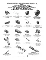
Page 30: ...T WILL FIT BIRO POWER CUTTERS MODELS 11 22 1433 33 34 3334 44 4436 55 EXCEPT WHERE NOTED OTHERWISE CONTACT YOUR NEAREST BIRO AUTHORIZED DISTRIBUTOR OR CONTACT BIRO MANUFACTURING Ph 419 798 4451 E Mail service birosaw com 28 ...

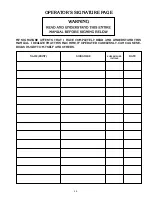
Page 31: ...E MY SIGNATURE ATTESTS THAT I HAVE COMPLETELY READ AND UNDERSTAND THIS MANUAL I REALIZE THAT THIS MACHINE IF OPERATED CARELESSLY CAN CAUSE SE RIOUS INJURY TO MYSELF AND OTHERS NAME PRINT SIGNATURE SUPERVISOR S INITIALS DATE 29 ...

Page 32: ...rformed only by a certified electrician BIRO is not responsi ble for service charges or labor required to replace any part covered by this limited warranty or for any damages resulting from misuse abuse lack of proper or recommended service EXCLUSION OF WARRANTIES AND LIMITATION OF REMEDIES BIRO gives no warranties other than those expressly stated in this limited warranty THE IMPLIED WARRANTY OF ...

Reviews: