9
Use SDI video output
Starting the Camera
After you have mounted the camera properly, connect the
camera to power.
Each time the camera is powered on, it will perform a self-
test to check the Pan/Tilt/Zoom (PTZ function). After self-
test, you can operate the camera.
NOTE!
• The self-test process starts after the camera is pow-
ered up. Please wait patiently.
• When the operating temperature is lower than zero
degrees Celsius, the camera will be automatically pre-
heat (the pre-heat process takes 30 minutes at most).
The self-test starts only after the temperature rises
above zero degrees Celsius.
Connect Camera to Monitor/SDI Device
To view your camera, you need to use the coaxial cable to
connect your camera to monitor or SDI device.
* The monitor/device must support the signal of HD-SDI or
3G-SDI.
Connect Camera with Controller
To control and configure your camera, you need to connect
with control system (or control keyboard) for communication
by RS-485/RS422. Set up the protocol of communication by
control keyboard, the camera can auto detect VISCA and
PELCO-D.
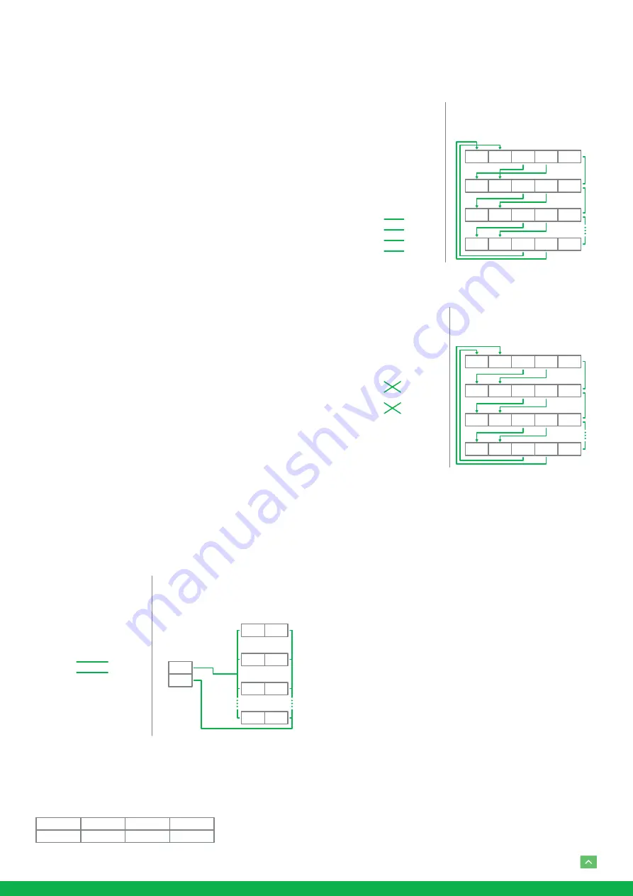
1. Connection
1.1 RS485 (PELCO D) control connection diagram
Connect the Camera’s RS485+ and RS485 to RS485/TX+ and
RS485/TX- on the control system/keyboard. The identity of
the control system or equipment may be different; the corre-
sponding relationship is as follows:
Camera
(RS485)
1. RX +
2. RX –
Keyboard
(PELCO P/D)
6. TX+
7. TX –
RS485 (PELCO D)
Multiple Cameras Connection
RX +
RX –
RX +
RX –
RX +
RX –
RX +
RX –
CAM1
SYSTEM /
KEYBOARD
(PELCO D)
CAM 2
CAM 3
CAM 255
RS485 PELCO D
System / Keyboard
Connection
TX –
TX +
RX +
RS 485 A
RS 485 +
RS 485 D+
RX –
RS 485 B
RS 485 –
RS 485 D–
1.2 RS422 (VISCA) control connection diagram
• SONY Keyboard RS422 Connection
• VISCA (None-Sony) Keyboard RS422 Connection
Setup Camera ID, Baud Rate and
Control Protocol
In order for you to control a camera, the camera ID, baud rate
and control protocol have to be set up in advance, Baud rate
and the camera ID setting on the camera have to be the same
as baud rate and camera ID setting on the system/control
keyboard. The camera can auto detect the VISCA and PEL-
CO-D, only need to set up the camera address and baud rate.
Connect the camera to a monitor. There is an initial setting
page displaying on the screen for 5 seconds when the cam-
era is powered on. On the page, it shows the factory default
setting of the camera ID, baud rate and other information.
Suggest taking a picture of this default setting information
for setting keyboard use. Set the keyboard or control system
to match the camera ID, baud rate setting with the camera.
1. Camera supports VISCA and PELCO-D protocols, proto-
col is detected automatically by the camera.
2. Factory Default Setting: For both SDI and IP video, Baud
Rate: 9600, Camera ID: 001, Pelco Protocol.
Camera
(RS422)
4. TX +
3. TX –
2. RX +
1. RX –
Keyboard
1. ---
2. ---
3. ---
4. ---
5. GND
6. RXD IN –
7. RXD IN +
8. TXD IN –
9. TXD IN +
RS422 (VISCA)
Multiple Cameras Connection
(SONY Keyboard)
RX +
RX –
TX +
TX –
GND
RX +
RX –T
X +
TX –
GND
RX +
RX –T
X +
TX –
GND
RX +
RX –T
X +
TX –
GND
KEYBOARD
CAM 1
CAM 2
CAM 7
SONY Keyboard
RS422 Connection
Camera
(RS422)
4. TX +
3. TX –
2. RX +
1. RX –
Keyboard
1. GND
2. RXD IN –
3. RXD IN +
4. TXD IN –
5. TXD IN +
RS422 (VISCA)
Multiple Cameras Connection
(VISCA Keyboard)
RX +
RX –T
X +
TX –
GND
RX +
RX –T
X +
TX –
GND
RX +
RX –T
X +
TX –
GND
RX +
RX –T
X +
TX –
GND
KEYBOARD
CAM 1
CAM 2
CAM 7
VISCA Keyboard
Connection
Summary of Contents for BDA200
Page 1: ...EYES A200 FULL NDI NO COMPROMISES USER GUIDE PART 1...
Page 16: ...16 Dimensions Unit mm 30 333 176 6 47 2 211 R75...
Page 17: ...17...
Page 18: ...18...
Page 19: ...19...
Page 20: ...WELCOME TO THE FUTURE bird dog tv hello bi rd dog tv...


