background image

Sensitivity

Optimal sensitivity can only be achieved with a thoroughly erased screen. Close contact of
the sample with the screen will also impact the imaging sensitivity. Ensure that the sample
is pressed close to the screen surface.  

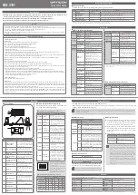
6.2  Problem Solving Guide

Problem 

Possible Cause 

Solution 

Scanner is not 
responding to host 
computer 

• 

Scanner door is open 

• 

Scanner is not on-line 

• 

USB cable is not connected 
to scanner or computer 

• 

USB cable is defective 

• 

Scanner is not turned on 

• 

Close Door 

• 

Press on-line button 

• 

Reconnect USB cable 


• 

Replace USB cable 

• 

Turn on scanner 

Image is not visible 
on the monitor 

• 

The ‘Transform” function in 
the software is set too high 

• 

(radioisotope only) 
Insufficient exposure time 

• 

Area where sample was 
placed was not scanned 

• 

Set to a lower maximum value 


• 

Expose sample for a longer 
time 


Check location of sample and 
rescan.                      


(radioisotopes) When imaging 

small screens ensure that the 
appropriate location template is 
used


Scans have image 
artifacts 

• 

Radioactive contamination on 
the phosphor surface coating 

• 

Static electricity on phosphor 
screen 

• 

Phosphor screen may be 
scratched or damaged 

• 

Contamination of sample tray 
with fluorescent material 


• 

Imager is not level and 
sample moved during scan 


• 

Diagonal line on a phosphor 
screen image 

• 

Check and clean using the 
protocols in this manual 

• 

Check and clean using the 
protocols in this manual 

• 

Visually inspect the screen 


• 

Clean sample tray with Bio-Rad 
cleaning solution, verify no 
residual contamination by 
scanning the sample tray. 

• 

Level imager, minimize liquid 
around sample and use sample 
holders to restrain sample from 
moving 

• 

The image was obtained by 
rescanning the screen. 

Scans have speckled 

images. 

• 

Dust on phosphor screen or 
fluorescent sample 


• 

Insure powder free gloves are 
used for handling screens and 
samples. 

34

Summary of Contents for PharosFX 170-7890

Page 1: ...s System 532 nm 170 7890 External Laser 488 nm 170 7892 External Laser 488 and 635 nm For Technical Service Call Your Local Bio Rad Office or in the US Call 1 800 4BIORAD 1 800 424 6723 This instrumen...

Page 2: ...thoroughly so that you fully understand the coverage it provides and are aware of your rights and responsibilities One of the responsibilities of system ownership is regular maintenance Following the...

Page 3: ...stem Location 11 3 1 2 AC Power Requirements 12 3 1 3 Host Computer Recommendations 13 3 2 System Setup 13 3 2 1 Shipping Check 13 3 2 2 Unpacking 13 3 2 3 Electrical and Communication Connections 15...

Page 4: ...30 5 2 3 Cleaning Imaging Screens 30 5 2 4 Storage of Imaging Screens 31 5 3 Exposure Cassette and Platform Maintenance 31 5 4 Screen Eraser Maintenance 31 5 4 1 Changing Bulbs 31 Section 6 Troublesho...

Page 5: ...portant to us To help you make informed decisions about safety we have provided comprehensive operating procedures and safety information in this manual and on labels affixed to instrumentation This i...

Page 6: ...the PharosFX or its accessories will void the manufacturer s warranty void the I E C 61010 and CDRH certification and create a potential safety hazard for the user Bio Rad Laboratories is not responsi...

Page 7: ...oduces laser energy of up to 10 milliwatts at 635 nm The cover of this system is designed to protect the user at all times Warning Do not remove the cover for any reason or defeat the interlock Attemp...

Page 8: ...color fluorescent signals The system is also capable of performing sequential detection of multiple fluorescent dyes on the same gel or blot Colorimetric Detection A Transilluminating Screen made of w...

Page 9: ...mated emission filter wheels with 6 filters These combined features permit the PharosFX to image almost any fluorescent dye and to scan multi color fluorescence applications in addition to storage pho...

Page 10: ...are reusable and unharmed by repeated exposure to radioactivity Screens are sensitive to particles and X rays All screens are flexible and easy to handle Exposure takes place in standard X ray casset...

Page 11: ...complete erasure process zeros or blanks the screen to a basal level which is critical for maximizing sensitivity linear response quantitative accuracy and image quality The Screen Eraser K is used w...

Page 12: ...occurs when a molecule absorbs light of a certain wavelength and excites electrons to a transient higher energy state Figure 2 6 step 1 When the electrons return to ground state energy is released in...

Page 13: ...ce signals are captured as a 16 bit digital file This file can then be analyzed and manipulated by the appropriate image analysis software for visualization and quantitation Traditionally the image is...

Page 14: ...2 9 Step 1 involves erasing the reusable phosphor screen to remove any background or residual image This normally takes 10 minutes The screens should be erased to the background level of 100 counts o...

Page 15: ...recommended that two people one on each side of the instrument lift the scanner from the bottom The scanner should be positioned on a level bench top with a minimum depth of 70 cm and a height clearan...

Page 16: ...All screen erasers must be plugged into a grounded electrical outlet Sample Exposure Cassettes The exposure cassettes do not require any power and can be placed in any convenient location where radioa...

Page 17: ...items and that no boxes are damaged If items are either missing or damaged report them to both the shipping company and Bio Rad Laboratories immediately The PharosFX system should arrive complete with...

Page 18: ...ransport of the PharosFX system Unlocking the Scan Head To protect the scanning mechanism during transport the scanner uses a scan head locking screw The screw which is located at the rear left hand s...

Page 19: ...ng for screen storage 3 2 3 Electrical and Communication Connections Power Insert the power cord into the power entry module on the rear panel of the scanner The scanner uses a universal power supply...

Page 20: ...ormation relating to the instrument version Figure 4 1 When the power is first turned on the LCD should display the sequence of messages shown below This process takes approximately 40 seconds Start u...

Page 21: ...tton on the control panel should be depressed only in the unlikely event that the acquisition software cannot halt scanner operation 4 2 Fluorescence Detection 4 2 1 Sample Preparation Prepare fluores...

Page 22: ...mm Gels should be wet Blots Membranes should be moist Use Sample Holders 170 7813 to keep sample from moving during scan When performing Colorimetric Gel Documentation work utilize the transilluminat...

Page 23: ...orescent Samples 1 Open the scan window in the acquisition software Under the File menu choose PharosFX In the acquisition window choose Select and use the layered menu to identi fy your application a...

Page 24: ...the two emission filter cubes Figure 4 4 To activate the switch simply depress once for each turn required Fig 4 4 Selecting a filter position using a filter wheel advance switch Caution Do NOT hold d...

Page 25: ...nstall a new filter hold the cube with the mounting slots on the left hand side Align the cube s mounting slots with the guides located on the filter wheel and gently push the cube onto the guides 6 R...

Page 26: ...on laser which is ideal for imaging fluorophores excited by 488 nm light The External Laser Module can also be outfitted with an additional 635 nm laser which further adds to the flexibility of the Ph...

Page 27: ...nts or performance of procedures other than those specified herein may result in hazardous laser energy exposure Caution The cover should be removed by trained service personnel only Do not attempt to...

Page 28: ...ser scanner Some users choose to dim the room lights to prevent accidental erasure When screens are not in use they should be placed in the original shipping box provided and placed in a dry and dark...

Page 29: ...10 Ensure that TLC plates are completely dry before placing them against the screen and always cover with plastic wrap to prevent flecks from contaminating the screen When imaging thick samples it is...

Page 30: ...om contaminating the imaging screen Wet thin samples should be completely enclosed in a heat sealable bag and moist samples must be covered with plastic wrap before being exposed to the imaging screen...

Page 31: ...he wrap or heat seal bag is wiped dry to minimize potential screen contamination 4 4 4 How to Use the Exposure Cassette Exposure Cassette K Fig 4 12 Steps in use of the Exposure Cassette K 1 Push the...

Page 32: ...ette and quickly place it on the sample tray with the phosphor surface facing upwards Note When transferring the screen from the exposure cassette to the scanner operator should minimize exposure to d...

Page 33: ...he highest resolution is 50 m and the lowest is 800 m Note Scanning phospor screens is a data destructive process so only one accurate scan can be performed per sample exposure 4 Select Acquire to beg...

Page 34: ...hor and render that portion of the screen unusable For the same reason the imaging screen should never be directly exposed to wet gels or chemicals Use some water imper meable media between a wet samp...

Page 35: ...en should be used only with H any other isotope will contaminate the screen 5 2 4 Storage of the Imaging Screens Always erase the screen prior to storage The surface of the screen should be completely...

Page 36: ...n the rear panel of the unit 6 Remove the white plastic filter 7 Remove the foam on both sides and replace the defective bulb 8 Reassemble by reversing steps 4 to 7 Step 6 Step 7a Step 7b Fig 5 Screen...

Page 37: ...should be lower than for a sample with a weak fluorescent signal Empirical testing of the proper PMT setting is required to obtain the best quality image If the preset PMT voltages are not satisfacto...

Page 38: ...r a longer time Check location of sample and rescan radioisotopes When imaging small screens ensure that the appropriate location template is used Scans have image artifacts Radioactive contamination...

Page 39: ...midity Storage Requirements 0 60 C 10 90 humidity External Laser Module Specification Dimensions 61 deep x 31 wide x 41 high cm Construction Welded 16 Gauge steel Weight 30 kg Electrical Input voltage...

Page 40: ...nt 3 Use of fittings or other spare parts not authorized by Bio Rad Laboratories 4 Inappropriate interfacing to external devices 5 Use of inappropriate solvents cleaning agents or samples 6 Non system...

Page 41: ...SYPRO Red Nile Red Radiant Red propidium iodide 170 7865 Filter 695 nm BP for Cy5 and Alexa Fluor 635 dyes 170 7867 Blank Filter Holder Sample Handling 170 7811 Glass Sample Tray 170 7812 Multi Sampl...

Page 42: ...ies Quantity One 1 D Analysis Software 170 9620 PDQuest 2 D Gel Analysis Software Basic License 170 9630 PDQuest 2 D Gel Analysis Software Advanced License Miscellaneous 931 0071 3 meter USB cable 161...

Page 43: ...Greece 30 210 777 4396 Hong Kong 852 2789 3300 Hungary 36 1 455 8800 India 91 124 2398112 3 4 5018111 6450092 93 Israel 03 951 4127 Italy 39 02 216091 Japan 03 5811 6270 Korea 82 2 3473 4460 Latin Ame...

Reviews: