BINMASTER WR-30 Series Instruction Manual Download Page 27

WR-30 Point-to-Point Wireless Bridge Instruction Manual 


27 


Troubleshooting 

If you are experiencing difficulties with your wireless installation, consult the troubleshooting steps listed 
below. For best results, identify the symptoms of the problem you are having and attempt all of the 
corrective actions listed for the particular symptom. 

Symptom 

Possible Cause 

Corrective Action 

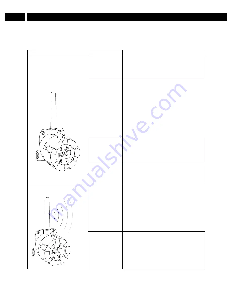
Devices will not connect. 


Devices have 
mismatched 
network IDs. 

•  Devices will not connect if they do not have 

the same network ID. Verify that both 
devices share the same network ID. 

Devices are out 
of range or there 
are obstacles 
blocking the 
wireless path. 

•  Bring devices closer together to see if it 

alleviates the issue. Units will display LINK 
OK if they are connected. If devices 
connect, consider placing closer together 
permanently, removing any obstacles, or 
mounting higher. 

•  Ensure antennas are on parallel plane. 

Devices that are vertically separated will not 
have as strong of a connection. 

•  If communicating over distance of miles, 

consider installing WR-30-RP repeaters or a 
high gain directional antenna. 

Multiple wireless 
devices in the 
area with the 
same ID. 

•  If there are multiple WR-30 wireless bridges, 

verify that each pair has its own unique 
network ID. 

Encryption keys 
do not match 

•  If using encryption, ensure that the 

encryption keys on both devices match 
exactly. 

Intermittent signal issues. 


Signal is too 
poor. 

•  Check RSSI. If signal is too low, consider 

moving devices closer together, clearing 
obstacles in wireless path, or mounting 
devices higher. 

•  Ensure devices are on parallel plane.  
•  If communicating over distance of miles, 

consider installing high gain directional 
antenna. 

Temporary 
obstacles are 
blocking the 
wireless path. 

•  Temporary obstacles, such as large trucks 

or heavy equipment, can interfere with 
wireless path. Consider moving wireless 
units higher or to an area with less traffic. 

?

Summary of Contents for WR-30 Series

Page 1: ...eplacement in a Rugged Industrial Housing Simple to Order Configure Install Range 1 Mile Line of Sight 500 ft Indoor Analog Digital Inputs and Outputs RS 485 Communications Remote or Attached Antenna...

Page 2: ...where malfunctioning could result in personal injury or property loss Anyone using this product for such applications does so at their own risk BinMaster shall not be held liable for damages resultin...

Page 3: ...re 16 Display Functions Messages 17 Primary Unit 17 Secondary Unit 18 Setup Menu 19 Entering Numeric Values 19 Primary Device Menus 20 Secondary Device Menus 23 Display Signal I O and Digital I O Stat...

Page 4: ...casts it to a second WR 30 unit The secondary unit then recreates that signal at its location The secondary unit may also transmit its own analog discrete or Modbus signals back to the primary unit Ju...

Page 5: ...1 5 pipe or wall mounting See Mounting Dimensions on page 31 for mounting space requirements Signal Connector Tightening Torque 2 5 lb in 0 28 Nm Shipping Dimensions 17 x 14 x 9 43 2 cm x 35 6 cm x 2...

Page 6: ...ut 24 dBm 250 mW Sensitivity 101 dBm RS 485 Modbus RTU Serial Comms Compatibility EIA 485 Connectors Removable screw terminal connector Max Distance 3 937 1 200 m max Baud Rate 1200 57 600 bps Data 8...

Page 7: ...e performed only by trained service personnel Service requiring replacement of internal components must be performed at the factory Installation All pushbuttons and wiring connectors are accessed by o...

Page 8: ...e may not cause harmful interference and ii this device must accept any interference received including interference that may cause undesired operation IMPORTANT The RF module has been certified for r...

Page 9: ...d on the base one internal and one external Static electricity can damage sensitive components Observe safe handling precautions for static sensitive components Use proper grounding procedures codes W...

Page 10: ...wireless device Power WR 30 and 2 Wire Transmitter from Same Power Supply The WR 30 wireless units may be powered from the same power supply that powers the 2 wire loop powered transmitter assuming th...

Page 11: ...itted wirelessly 4 20 mA Output Connector The 4 20 mA output corresponds with the analog input signal on the paired wireless device The analog output signal is always 4 20 mA regardless of the input t...

Page 12: ...igital output Modbus RTU Serial Communications The WR 30 acts as a simple pass through for Modbus communications As such multiple Modbus enabled devices may be transmitted wirelessly using the WR 30 W...

Page 13: ...ection The calibration equipment is certified to NIST standards Overview There are no jumpers to set for wireless device input selection Setup and programming is done through the programming buttons l...

Page 14: ...Signal Strength Indicator Indicates the wireless signal strength between wireless devices on a scale of 1 to 10 Enter Select a menu item of option RT Receiving Transmitting Flashes while the devices...

Page 15: ...order to ensure that the correct signals are reaching the units Pressing either the previous or display buttons while the device is in run mode will cycle through the unit s display modes which are i...

Page 16: ...face underneath the enclosure cover Use of WR Manager is required for programming advanced settings such as wireless encryption and analog signal calibration Note Units must be powered externally pri...

Page 17: ...tion to input OUTPUT Set the selected digital connection to output DIGITAL I O 2 Displays digital connection 2 s current setting press enter to change DIGITAL I O 3 Displays digital connection 3 s cur...

Page 18: ...on NETWORK ID Displays the point to point wireless network ID press enter to change 01 99 The network ID can be any number between 01 and 99 ANALOG INPUT Displays the current analog input type press e...

Page 19: ...tion will be an output on the secondary unit Because of this the secondary wireless unit has fewer menu options than the primary unit Primary Device Secondary Device Entering Numeric Values Numeric va...

Page 20: ...input is capable of accepting a 0 to 10 VDC signal 0 to 5 VDC signal or 1 5 VDC signal Digital I O Setup All four digital connections may be set as either inputs or outputs The setting on the primary...

Page 21: ...meout sets the length of time the wireless devices will wait for a reply from the other Modbus device before returning an error This should be 1 to 2 seconds at 9600 bps on the primary device Modbus B...

Page 22: ...u will be required to enter that password before being allowed to access the device menu Note Setting a password will require you to enter the password to access the device settings via the PC softwar...

Page 23: ...ary device has fewer menu options than the primary device shown below Display Signal I O and Digital I O Status Pressing either the previous or display buttons while the device is in run mode will cyc...

Page 24: ...can be found on the included CD Once the software is running power the unit using a 12 28 VDC power supply and connect the device to the PC using the provided USB cable The PC will automatically insta...

Page 25: ...WR 30 Point to Point Wireless Bridge Instruction Manual 25 Calibration Analog Input Calibration 4 20mA Output...

Page 26: ...evice communication can be secured by enabling 128 bit AES encryption A channel mask may also be set for interference immunity The encryption key and channel mask may be entered on the Advanced tab On...

Page 27: ...mounting higher Ensure antennas are on parallel plane Devices that are vertically separated will not have as strong of a connection If communicating over distance of miles consider installing WR 30 R...

Page 28: ...ices Check wiring diagrams starting on page 9 Digital inputs are not corresponding with digital outputs Devices have mismatched input output settings Check to make sure the digital connection is progr...

Page 29: ...be downloaded at www binmaster com USB cable is faulty Try connecting the wireless device using a known good micro USB cable Any standard USB A to micro USB B cable such as the one used to charge a s...

Page 30: ...for the particular application Model ___________________ S N __________________ Date _______________ Primary Parameter Default Setting User Setting ANALOG INPUT 4 20mA DIGITAL I O 1 INPUT DIGITAL I O...

Page 31: ...ons Side Cross Section View Note The supplied conduit plug may extend up to 0 6 in 15 mm from the conduit opening when installed PDA6963 BM Stainless Steel Pipe Mounting Kit Figure 11 PDA6963 BM Stain...

Page 32: ...Garner Industries 7201 North 98th Street Lincoln NE 68507 9741 402 434 9102 www binmaster com P O Box 29709 Lincoln NE 68529 Fax 402 434 9133 Email info binmaster com 925 0381 LIMW30BM_A SFT102 Ver 1...

Reviews: