


WR-30 Point-to-Point Wireless Bridge Instruction Manual
19
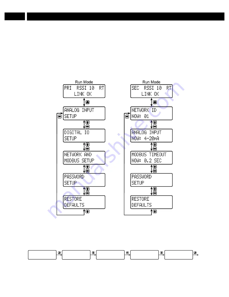
Setup Menu
The setup menu consists of analog, digital (discrete), and Modbus
®
input/output settings, network ID,
password, and factory defaults restoration.
The
primary
wireless unit determines network protocol and digital I/O settings for the
secondary
unit,
simplifying the setup process. For instance, if a digital connection is programmed to be an
input
on the
primary
unit, that same connection will be an
output
on the
secondary
unit. Because of this, the
secondary
wireless unit has fewer menu options than the
primary
unit.
Primary Device
Secondary Device
Entering Numeric Values
Numeric values are set using the
next
and
previous
buttons. Press
next
to select next digit and
previous
to increment digit value.
The selected digit will flash.
Press the
enter
button, at any time, to accept the value or the
menu
button to exit without saving.
NOW: 01
NETWORK ID
SET: 01
NETWORK ID
SET: 11
NETWORK ID
SET: 11
NETWORK ID
SET: 12
NETWORK ID
Access
edit mode
Increment
selected digit
Select the
next digit
Increment
selected digit
Accept
new value


