14
Upper Control Box
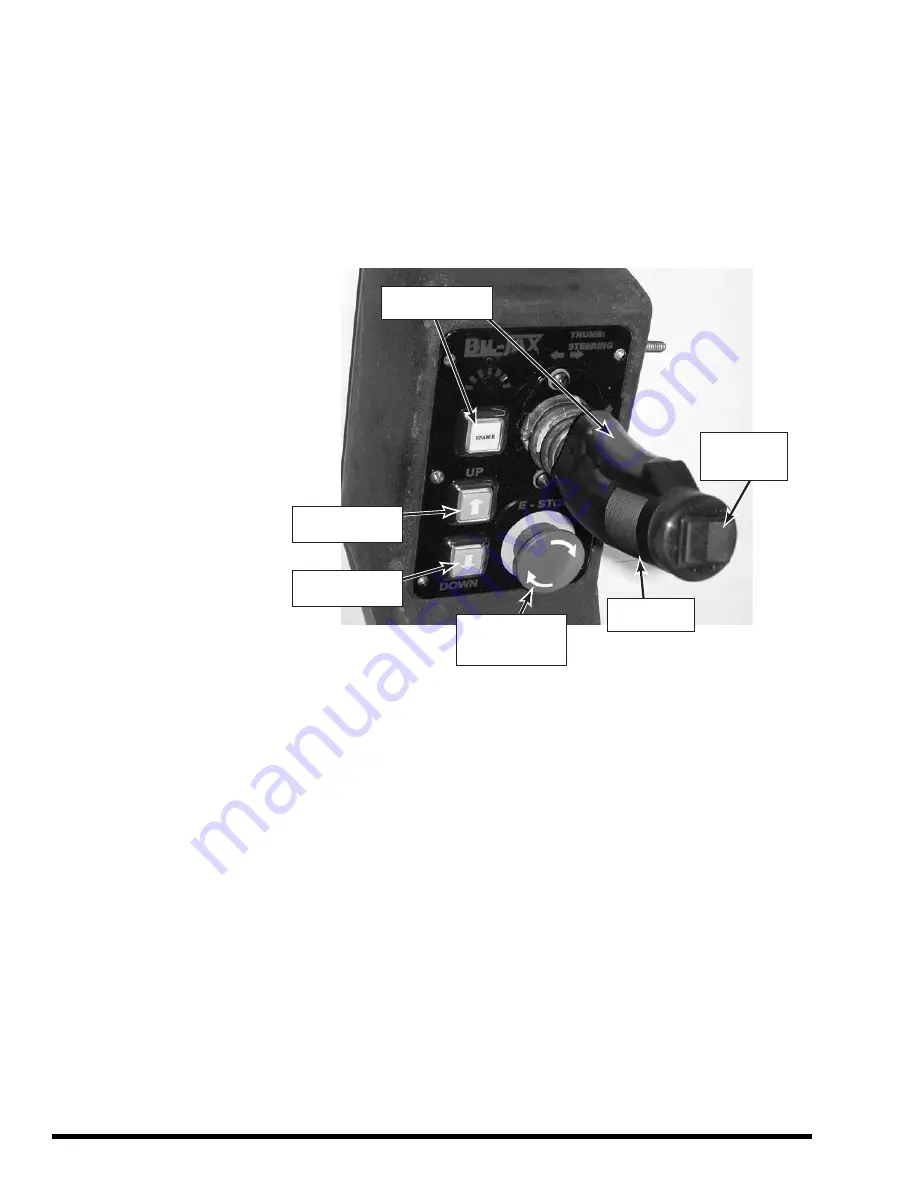
The upper control box, Figure 3-2, is in the lift cage. The upper control box
enables lift and travel operations whenever the BATTERY ON/OFF switch is in
the ON position and the lower control box key switch is in the UPPER CONTROL
position.
Upper control box controls include four pushbuttons and a forward/reverse floor-
travel joystick with thumb-switch steering.
TRAVEL
JOYSTICK
STEERING
THUMB
SWITCH
ENABLE
PUSHBUTTONS
EMERGENCY
STOP
PUSHBUTTON
UP
PUSHBUTTON
DOWN
PUSHBUTTON
Figure 3-2. Upper Control Box
Press and hold either one of the ENABLE pushbuttons to enable a control
function. An ENABLE pushbutton must be pressed to enable the lift, steering,
and travel functions. The ENABLE pushbutton must be held down to continue the
equipment function.
With one of the ENABLE pushbuttons depressed, press the UP [ ] pushbutton
to raise the platform or press the DOWN [ ] pushbutton to lower the platform.
With one of the ENABLE pushbuttons depressed, move the travel joystick
forward or back to move the lift vehicle in the forward or reverse direction. For
slow speeds, move the joystick forward or back just a little. For faster speeds,
move the joystick more.
With one of the ENABLE pushbuttons depressed, press the left or right side of
the thumb switch to steer the rear wheels to the left or right. The steering can be
adjusted before or during floor travel.
Press the EMERGENCY STOP button to stop all equipment motion. If the lift
vehicle is moving forward or back, a travel brake is applied causing travel to stop.
To resume lift vehicle operations, turn EMERGENCY STOP button clockwise.
Summary of Contents for ESP 19
Page 1: ......
Page 18: ...18 ...
Page 42: ...42 Figure 4 17 Electrical Layout ...
Page 43: ...43 Figure 4 18 Drive Wiring Diagrams ...
Page 44: ...44 Figure 4 18 Drive Wiring Diagrams 2 ...
Page 45: ...45 Figure 4 19 Upper Control Wiring Diagram ...
Page 46: ...46 ...
Page 49: ...49 Figure 5 1 Decal Locations Side View ...
Page 51: ...51 APPENDIX A PART LISTS ...
Page 68: ...68 DRIVE AXLE 16 17 15 12 11 10 14 13 9 8 7 5 4 6B 6 6A 6C 1 2 3 ...
Page 78: ...78 HYDRAULIC CYLINDER FITTINGS AND HOSES 1 9 10 11 12 13 14 15 14 8 5 4 3 2 6 7 16 17 ...
Page 80: ...80 ...
Page 82: ...82 EUCLID MOTOR FACE MOUNT ...
Page 84: ...84 EUCLID MOTOR FLANGE MOUNT ...
Page 86: ...86 ASI MOTOR MOUNT ...
Page 88: ...88 STEERING ASSEMBLY I ...
Page 90: ...90 STEERING ASSEMBLY II ...
Page 92: ...92 ...
Page 93: ...93 ...
Page 94: ...94 ...
Page 95: ...95 ...
Page 96: ...96 ...


