background image

Bike Sport Developments Ltd  
Tel 0044 (0)1327 263942 

–  

[email protected]

 / 

www.bikesportdevelopments.co.uk


Manual revision 09, 07/11/2015 


11 

Bike Sport Developments Ltd  
Unit 3D Manor Business park, Grants Hill way, Woodford Halse, Northants, NN11 3UB - UK 

Tel: 0044 (0)1327 263942 
Copyright 

– Bike Sport Developments Ltd - 2015


USB 

– PC interface device BB-UCIF 


1.  PC operating systems from Windows 7 to Windows 10 are OK 

to use. If you have an older PC with XP then please Email us 
for specific drivers. 
 

2.  Download and install the latest USB drivers at 

www.bikesportdevelopments.co.uk/blipbox

 , even if your PC is 

news and the COM port says it is working correctly, it may not 
be fully updated. 

a.  The download is a zip file that you should copy to 

any location on your C drive. 

b.  Now look in that folder and un-zip the new drivers to 

leave you with an 

exe

 file 

c. 

Double click the 

exe

 file to run the new driver 

installation. 

d.  Re-start your PC. 


3.  Now plug in the USB adapter and wait for up to a minute 

(sometimes 2) for the drivers to install correctly. 


4.  Open the 

Control Panel

 , then look for the 

System

 icon , then 

Device Manager

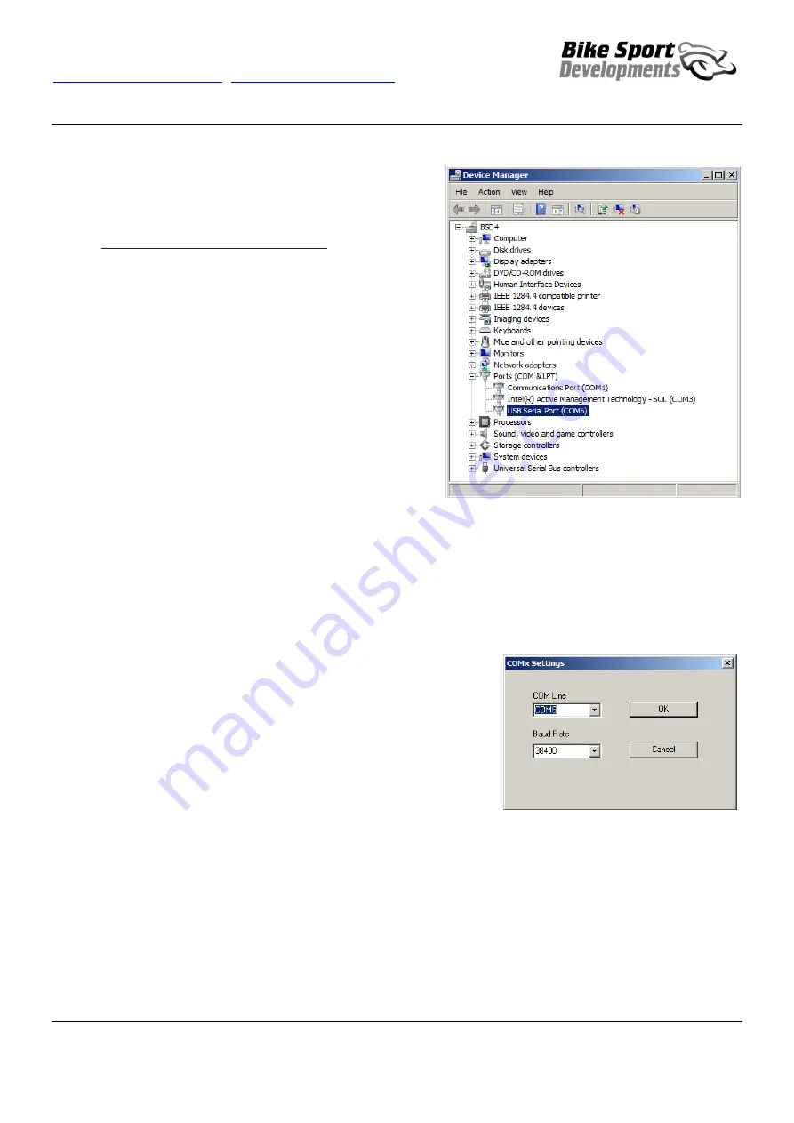
 to view this window: 

 
This icon shows that the USB adapter is installed and working but it is 
still worth checking that the drivers have updated. Simply ‘right click’ 
this COM line and select ‘update driver’ 
 
Let the PC search automatically and if no updates are found then all is OK. 
 
Look at the COM number that has been allocated and make a note of this as it will be used in the WinBLIP software. In this 
example it is COM6 
 
Note also that you may get a different COM number if using different USB ports on your PC, so try to use the same one each 
time. 
 
 
Open WinBLIP and go to 

Setup

 / 

COM settings

 from the upper menu 

 
It should look like this with the Baud Rate at 38400 and the COM line set to the 
one you noted in the Device manager. 
 
If it does not, then use the pull down arrows to change things. 
 
Then press 

OK


You should now have communication. 


Summary of Contents for Blip Box-Pro

Page 1: ...erent rider tracks gear ratios and foot rest hardware System may be re programmed or adjusted by the additional USB interface and the WinBLIP software Sold as a separate part Machined aluminium housing with fully sealed electronics and high specification plug n play wiring no wiring modifications needed Designed and made in the UK by Bike Sport Developments Ltd How it works The Yamaha R1uses a Rid...

Page 2: ...y to make a clutch free downshift while accelerating like dropping a gear to overtake In this case the BLIP system will not work After each downshift blip release the lever pressure to re arm it for the next gear Blip change IMPORTANT When first plugged in you will see the LED blinking an error code for 30 seconds This is perfectly normal during the installation because the CAN connector provides ...

Page 3: ...e the system self calibrates at power ON to shift this back to 2 5v internally even if a multi meter shows an error The system has a maximum self calibration of 0 5v beyond this the sensor is considered to be permanently damaged Stretching PULL the load cell up shift has a typical set point of 2100 mV a change of 0 4v Compressing PUSH the load cell creates a higher voltage with the default BLIP th...

Page 4: ...nsor will PULL to create an up shift In the race pattern shift layout shown on the right the sensor will PUSH to create an upshift Typical values for standard shift pattern Up shift 2100Mv Blip shift 2850Mv Typical values for race shift pattern Up shift 2900Mv Blip shift 2150Mv UP Shift DOWN Shift PULL UP shift reducing voltage PUSH Down shift rising voltage A B UP Shift DOWN Shift PULL Down shift...

Page 5: ...side near the front sprocket D 4 way black connector socket contacts for the throttle twist grip signals of the throttle body under air box E 4 way black connector pin contacts for the twist grip output signals feeding into the bike loom under air box F 4 way white connector pin contacts for linking to the CAN bus diagnostic port under the seat under seat G 4 way white connector socket contacts as...

Page 6: ...ke Note that it helps to temporarily disconnect the air pressure sensor and throttle motor when routing the Blip Box wiring Use cable ties as necessary to retain the wiring Note 2 IMPORTANT Connector E is 3D printed and due to production tolerances on the latch it should be secured with a cable tie across the 2 connectors to ensure it cannot come apart See image 2 at right inside the blue ring You...

Page 7: ...the fuel tank support has been removed The Blip Box module rests inside the rear of the sub frame alongside the exhaust valve motor The kit contains strips of foam rubber to isolate from vibration but mainly to hold the component in place Remove the rubber shroud from the CAN bus connector ringed in blue and re fit this to connector G of the Blip Box loom Not re fit connector G to the original mou...

Page 8: ...or less than 30 seconds When you turn ON the ignition 1 In this case the Blip Box module never actually turned off so there are no LED indicators or self calibration Normal ignition OFF sequence 1 First you will hear the main bike relay click off 2 Blip Box will display a 2 x blink error code as the throttle grip signals go out of range when the ECU turns off 3 The CAN data from the ECU also stops...

Page 9: ...rip connector Check wiring If wiring is OK and there is no diagnostic for the Grip Inputs signals it suggest a damaged sensor Note This diagnostic is also used for the self calibration at power ON and lasts approximately 20 seconds 4 blinks short gap Battery voltage out of range 8 5v to 16 5v 5 blinks short gap Load cell error If less than 1 5v or greater than 3 5v for longer than 1 2 seconds In t...

Page 10: ...oad selection and look at the lower left of your screen to see when the download is complete You may have a waring then some downloads may harm your computer just change this to Keep not Discard 2 Double click this Blip Box setup exe at the lower left to start the installation process 3 You can choose to keep the default install folder or change to one you prefer 4 When complete you will have a ne...

Page 11: ...file to run the new driver installation d Re start your PC 3 Now plug in the USB adapter and wait for up to a minute sometimes 2 for the drivers to install correctly 4 Open the Control Panel then look for the System icon then Device Manager to view this window This icon shows that the USB adapter is installed and working but it is still worth checking that the drivers have updated Simply right cli...

Page 12: ... hysteresis so it would be 2200 ON and 2250 OFF example values only c The signals must also be above the threshold for longer than the 10mSec validation time 3 The Blip Box generates a switch output signal to replicate the original shifter switch on the R1 this is routed back into the ECU via the original shifter connector a Most of the shifter controls are still maintained within the ECU as befor...

Page 13: ... is applied when you select Power 3 or Power 4 but the values in the map are designed for use with Power 4 c If you ride in power mode 3 then you may need to adjust these values to suit 6 The Gear Shift BLIP gain is a multiplier applied to the base BLIP values This enables a higher blip value in lower gears Example a Gain of 110 would multiple the BLIP value by 1 10 10 extra 7 BLIP Hold This is th...

Page 14: ...he BLIP is currently inhibited by one or more reasons 6 Live data a Throttle grip 1 Input Mv b Throttle grip 2 Input Mv c Load cell Mv d Load cell offset self calibration adjustment after power ON e Engine power mode 1 4 f Engine RPM g TPS Throttle grip h GEAR 0 is neutral i Rear wheel speed in kmh 7 These icons will light up if one of the diagnostic flashing LED is active 8 Restart system re star...

Page 15: ...deLoadMCB cmd file Double click this file and the load procedure will begin Remember to load the BLIP map file after any module re flash This system is intended for off highway performance use only It is not certified for use on the road Application Yamaha R1 2015 onwards Components Part No Qty Blip Box control module version C onwards BBM C 1 Main wiring loom BDW1607_03 1 Shift load cell 520mm ca...

Page 16: ...nor Business park Grants Hill way Woodford Halse Northants NN11 3UB UK Tel 0044 0 1327 263942 Copyright Bike Sport Developments Ltd 2015 Bike Sport Developments Ltd Unit 3D Manor Business Park Grants Hill way Woodford Halse Northants NN11 3UB UK Tel 0044 0 1327 263942 www bikesportdevelopments co uk Download the software drivers and PDF manuals at www bikesportdevelopments co uk blipbox ...

Reviews: