Board Layout
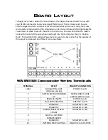
To begin, let’s have a look at the board layout. The diagram below should line up with
your BEMS Commander Series Sovereign Effects Board. The terminals each have an
effect assigned to them and your LED’s will and switches will connect using the screw
terminals by simply inserting the stripped wire into the terminal and then tightening the
screw down in place to secure the wire in the terminal. You may find it best to make a
hook with the end of the wire when inserting it into the terminal so that it’s “double
thick.” That will help the terminal have more to secure to. Also note that the polarity of
the output terminal will be different for some effects.
SOVEREIGN Commander Series Terminals
TERMINAL
EFFECT
POLARITY/CONNECTION
1(RX)
NAVIGATION LIGHT
(Alternate version)
POSITVE to LED
2
SWITCH INTERIOR DIMMER
UP
SWITCH WIRE 1 HERE
SWITCH WIRE 2 to GR
3
IMPULSE ENGINE
POSITVE to LED
4
SAUCER NAVIGATION
POSITIVE to LED
5
BUSSARD 1
NEGATIVE to LED
6
BUSSARD 2
NEGATIVE to LED
7
BRIDGE/NACELLE/BELLY
STROBE
NEGATIVE to LED
8
SWITCH – INTERIOR
DIMMER DOWN
9
BUSSARD 3
NEGATIVE to LED
10
INTERIOR STRIP LIGHTING
NEGATIVE to LED STRIPS


