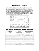
Board Layout Description
2 - SWITCH INTERIOR DIMMER DOWN
– This terminal controls the switch for the
interior strip brightness down. If you are using a double rocker switch, connect the
down arrow pole to this terminal and the ground (center) pole to the GR terminal. If you
are using a single switch, connect one pole on the switch to this terminal and the other
to GR.
3 - IMPULSE ENGINE
– (do not use if using the Captain Series Upgrade) This terminal
controls the basic impulse engine effect. Connect the POSITIVE leg of your impulse LED’s
(with proper resistor) to this terminal. The NEGATIVE leg of the impulse LED’s will
connect to GR. NOTE: If you are using the Captain Series Upgrade, you will use the
Impulse Engine terminal on that board INSTEAD of this terminal.
4 - SAUCER NAVIGATION
– This terminal controls the starboard (green) and port (red)
navigation lights on the saucer. Connect the POSITIVE leg of your navigation LED’s (with
proper resistor) to this terminal. The NEGATIVE leg of the navigation LED’s will connect
to GR.
5 - BUSSARD 1
– This terminal (along with terminals 6 and 9) controls one of the three
LED’s used in the bussards for the “lava” effect. All three LED’s work in conjunction to
make the effect work. Just arrange them in a triangle inside the front of the nacelle,
adjusting them until you are satisfied with the look. The NEGATIVE leg of your bussard
LED 1 will connect here. The POSITIVE leg (with proper resistor) will connect to 9V.
6 - BUSSARD 2
- This terminal (along with terminals 5 and 9) controls one of the three
LED’s used in the bussards for the “lava” effect. All three LED’s work in conjunction to
make the effect work. Just arrange them in a triangle inside the front of the nacelle,
adjusting them until you are satisfied with the look. The NEGATIVE leg of your bussard
LED 1 will connect here. The POSITIVE leg (with proper resistor) will connect to 9V.
7 - BRIDGE/NACELLE/BELLY STROBE
- This terminal controls the faster strobe lights on
the saucer behind the bridge, on the belly, and on the rear of the nacelles. Connect the
NEGATIVE leg of your strobe LED’s to this terminal. The POSITIVE (with proper resistor)
leg of the LED’s will connect to 9V.
8 - SWITCH INTERIOR DIMMER UP
- This terminal controls the switch for the interior
strip brightness up. If you are using a double rocker switch, connect the up arrow pole
to this terminal and the ground (center) pole to the GR terminal. If you are using a single
switch, connect one pole on the switch to this terminal and the other to GR.


