background image

13

Installation, Operation and Maintenance Manual

MAN616_EAC Rev. 5

July 2020

Section 2: Installation

Installation

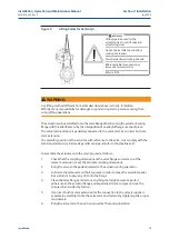
Figure 9 

Lifting Points for ALGAS-QA


!

WARNING

Any lifting method different from what described above is strictly  forbidden. 
Biffi reject any responsibility for damages to goods or injuries to persons coming from 
wrong lifting operations.

The actuator can be assembled onto the valve flange either by using the actuator-housing 
flange with threaded holes, or by the interposition of an adaptor flange or a spool piece. 

The actuator drive sleeve is generally connected to the valve stem by an insert bush or a 
stem extension.

The assembly position of the actuator, with reference to the valve, must comply with the 
plant requirements (cylinder axis parallel or perpendicular to the pipeline axis).

To assemble the actuator onto the valve proceed as follows:

1. 

Check that the coupling dimensions of the valve flange and stem, or of the 
relevant extension, meet the actuator coupling dimensions.

2. 

Bring the valve to the position related to the actuator spring operation.

3. 

Lubricate the valve stem with oil or grease in order to make the assembly easier. 
Be careful not to pour any of it onto the flange.

4. 

Clean the valve flange and remove anything that might prevent a perfect 
adherence to the actuator flange and especially all traces of grease, since the 
torque is transmitted by friction.

5. 

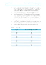
If an insert bush or stem extension for the connection to the valve is supplied 
separately, assemble it onto the valve stem and fasten it by tightening the proper 
stop dowels.

6. 

Bring the actuator to the position caused by the spring operation.

Lifting lugs to be used for the 

actuator only. Do not lift valve and 

actuator together.

Do not disassemble top or bottom 

cover spring loaded.

Porential electrostatic charge hazard.

Biffi is not liable for any personel 

injury due to incorrect use.

Refer to IOM.

Summary of Contents for ALGAS Series

Page 1: ...n Pneumatic Actuator Copyright Biffi The information in this document is subject to change without notice Updated data sheets can be obtained from our website www biffi it or from your nearest Biffi Center Biffi Italia s r l Strada Biffi 165 29017 Fiorenzuola d Arda PC Italy PH 39 0523 944 411 biffi_italia biffi it ...

Page 2: ...hecked Approved 5 July 2020 General update Migration to new template 4 March 2018 Updated Section 2 2 Ermanni Orefici Vigliano 3 January 2017 Updated applicable regulation Section 1 1 1 and 1 2 Ermanni Orefici Vigliano 2 April 2016 Updated applicable regulation Section 1 1 1 Ermanni Orefici Vigliano 1 January 2015 Issue document Lazzarini Orefici Vigliano ...

Page 3: ...Use 3 1 Operation Description 17 3 2 Residual Risks 18 3 3 Operations 18 3 4 Calibration of the Quick Operation Time 19 3 4 1 By pass Adjustment 19 3 5 Setting of the Angular Stroke 21 3 5 1 One Travel stop screw Screwed on the End Flange Center of Pneumatic Cylinder 22 3 5 2 Angular Stroke Setting in Case of Two Travel Stop Screws in the End Flange of Pneumatic Cylinder 24 3 5 3 Stop Screw Screwe...

Page 4: ...als 34 5 2 1 1 Seals Replacement 34 5 2 1 2 Cylinder Reassembling 35 5 3 Lubrication of Mechanism 38 5 4 Dismantling and Demolition 39 Section 6 Troubleshooting 6 1 Failure or Breakdown Research 40 Section 7 Layouts and Sectional Drawings 7 1 Parts List for Maintenance and Replacing Procedure 41 Section 8 Spare Parts 8 1 Spare Parts 47 Section 9 Date Report for Maintenance Operations Date Report f...

Page 5: ...and safety instructions for use in hazardous Area TR TS 004 2011 Customs Union Technical Regulation For safety of low voltage equipment TR TS 010 2011 Customs Union Technical Regulation For safety of equipment and machines TR TS 012 2011 Customs Union Technical Regulation For safety of equipment operated in explosive atmosphere TR TS 020 2011 Customs Union Technical Regulation Electromagnetic Comp...

Page 6: ...conditions are specified in the documentation forwarded together with the product This warranty does not cover special products or components not warranted by subcontractors or materials that were used or installed improperly or were modified or repaired by unauthorized staff In the event that a fault condition be caused by improper installation maintenance or use or by irregular working condition...

Page 7: ...the valve stroke avoiding possible impact damages to the valve trim and to the actuator itself The spring return pack incorporates up to four springs fully encapsulated in a factory welded cartridge this ensures safety to personnel and simplifies assembly The spring action can be easily changed in the field from to close in to open or from to open in to close modular design The angular stroke of t...

Page 8: ...c Actuators ALGAS Series Coding System The expected lifetime of actuator is approximately 25 years Code ALGAS XXX K YYYYY ZZZZ F S Actuator series Actuator model Scotch yoke version C Canted S Symmetric Spring cartridge model Cylinder size Internal diameter in mm Fail safe action CL Spring to close OP Spring to open Service Standard QA Quick acting ...

Page 9: ...xcellent finish these conditions are guaranteed by an individual inspection certificate in order to maintain these characteristics until the actuator is installed on the plant it is necessary to observe a few rules and take appropriate measures during the storage period 1 Make sure that plugs are fitted in the air connections and in the cable entries The plastic plugs which close the inlets do not...

Page 10: ...e in accordance with ISO 5211 but for actuator models 0 3 to 6 the holes are drilled on the centreline in order to allow an easier assembly of an intermediate flange when required This intermediate flange or spool piece can be supplied when the valve flange cannot directly match the actuator flange in its standard configuration For the biggest actuator models the actuator flange can be machined in...

Page 11: ...0 Section 2 Installation Installation Figure 2 Coupling Dimensions for Scotch Yoke Standard Actuators Drive sleeve H max N 4 holes flange N 8 holes flange N THREADED HOLES P C D number and size according to ISO 5211 but the holes are on centerline instead of straddle the centerline ø d1 max Flow line Top view of the scotch yoke mechanism actuator shown in closed position Models from 0 3 to 6 Dimen...

Page 12: ... and Maintenance Manual MAN616_EAC Rev 5 Section 2 Installation Installation Drive sleeve H max N 16 holes flange N 12 holes flange N THREADED HOLES P C D number and size according to ISO 5211 ø d1 max Flow line Top view of the scotch yoke mechanism actuator shown in closed position Models 14 18 32 35 42 Figure 3 Coupling Dimensions for Scotch Yoke Standard Actuators Dimensions in millimeters Actu...

Page 13: ...n Installation Drive sleeve H max N 16 holes flange N 12 holes flange N THREADED HOLES Flange sizing according to ISO ø d1 max Flow line Top view of the scotch yoke mechanism actuator shown in closed position Models 50 60 Figure 4 Coupling Dimensions for Scotch Yoke Standard Actuators Dimensions in millimeters Actuator model Ø d1 Ø d2 Ø d3 Ø d4 N h1 h2 H max Ø d5 W K Table 4 Size Table ...

Page 14: ...ons according to the following figure Figure 5 Insert Bush Intermediate Coupling Flange Position 2 Position 3 Position 4 Rotate insert bush 180 around vertical standard position 1 Rotate insert bush 180 around axis A A from position 2 Rotate insert bush 180 around axis A A from position 1 Insert bush turned upside down The Biffi insert bush with 2 external keys at 45 allows to position the keyway ...

Page 15: ...ce Avoid the lifted actuator to be hung above the personnel WARNING The actuator must be lifted by means of a suitable lifting apparatus The weight of the actuators is indicated in the technical documentation attached to the equipment itself For lifting and moving the actuator use only hooks fitted with safety latch like the one for example shown in Figure 6 Figure 6 Example of hook with safety la...

Page 16: ...oints for ALGAS QA For lifting unbalanced loads use ropes of different lengths or chains with adjustable length Check each time the conditions of all lifting equipment used and discard it if not in perfect working order Do not knot or twist the ropes so as not to reduce the lifting capacity or produce torsional effects on the load being lifted Use the utmost caution and remain at a safe distance f...

Page 17: ...ceed as follows 1 Check that the coupling dimensions of the valve flange and stem or of the relevant extension meet the actuator coupling dimensions 2 Bring the valve to the position related to the actuator spring operation 3 Lubricate the valve stem with oil or grease in order to make the assembly easier Be careful not to pour any of it onto the flange 4 Clean the valve flange and remove anything...

Page 18: ...tem enters the actuator drive sleeve This coupling must take place without forcing and only with the weight of the actuator When the insert bush has entered the actuator drive sleeve check the holes of the valve flange If they do not meet with the holes of the actuator flange or the stud bolts screwed into them the actuator drive sleeve must be rotated feed the actuator cylinder with air at proper...

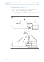
Page 19: ... actuator can also be lifted to assemble directly onto the valve with stem with horizontal axis To make a correct lifting procedure proceed as follow 1 Connect properly the actuator lifting points 1 with chains and connect by suitable slings the support brackets 2 and 3 Lifting eyelets 1 Support brackets 2 Support brackets 3 Lifting eyelets 1 Figure 10 ...

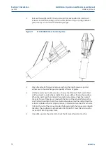
Page 20: ...r to the valve in such a way that the insert bush assembled on the valve stem enters the actuator drive sleeve without forcing the coupling When the insert bush has entered the actuator drive sleeve check the holes of the valve flange If they do not meet with the holes of the actuator flange or the stud bolts screwed into them the actuator drive sleeve must be rotated feed the actuator cylinder wi...

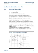
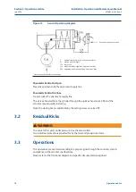
Page 21: ...lot of the fast discharge valve the opening of the latter is determined the fast discharge of motor fluid the quick extension of the spring and the consequent fast operation of the actuator The motor fluid going out from one chamber of the cylinder partially returns in the other chamber and partially flows through the discharge line The last part of the cylinder stroke is strongly slowed down by a...

Page 22: ...ssurize the pneumatic supply line The air is exhausted from the cylinder through the quick exhaust valve 285 and the actuator moves quickly in closing Note the closing time is adjustable by the setting screw on valve 285 3 2 Residual Risks WARNING The actuator has parts under pressure Use the due caution Use individual protections provided for by the laws and provisions in force 3 3 Operations The...

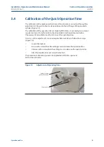
Page 23: ...mer requirements and to technical data sheet included in technical documentation If necessary it s possible to modify or to re set the operating time To carry out the adjustment use an adequate Allen wrench and follow these steps Figure 14 Loosen the locknut Screw with a screwdriver the setting screw to increase the operation time Unscrew with a screwdriver the setting screw to decrease the operat...

Page 24: ...clockwise to increase throttling action and consequently to slow the last part of cylinder stroke To decrease throttling action turn the needle for by pass in anti clockwise direction To reduce more the operating time higher speed unscrew both By pass screws see diagram in Figure 15 NOTICE To correctly calibrate the quick operation time it is necessary to arrange the data acquisition using a posit...

Page 25: ...he travel stop screw on the right side of the actuator 3 5 1 One Travel stop screw Screwed on the End Flange Center of Pneumatic Cylinder Suitable only for ALGAS QA models that no need damper action to reduce the operating time in the last part of the cylinder stroke For the adjustment of the travel stop screws proceed as follows See Figures 16 and 17 on the next pages 1 Loosen the lock nut 2 with...

Page 26: ...5 30 41 100 30 41 135 30 30 175 30 30 235 30 30 July 2020 Installation Operation and Maintenance Manual MAN616_EAC Rev 5 Section 3 Operation and Use Operation and Use Pneumatic Cylinder Size Wrench C1 mm Wrench C2 mm Figure 16 Table 7 ...

Page 27: ... 55 735 17 55 785 17 55 835 17 55 885 17 55 935 17 55 1000 17 55 1100 17 55 1200 17 55 1300 17 80 1450 17 80 Installation Operation and Maintenance Manual MAN616_EAC Rev 5 July 2020 Section 3 Operation and Use Operation and Use Pneumatic Cylinder Size Wrench C1 mm Wrench C2 mm Table 8 Figure 17 ...

Page 28: ...flange of the pneumatic cylinder proceed as follows see Figure 18 and table 9 on page 26 1 Supply pressure to the cylinder to reduce trust on the stop screws 2 Unscrew the lock nuts d with a proper wrench c2 3 Adjust the travel stop screws g with a proper wrench c1 4 Rotate anticlockwise to increase the angular stroke rotate clockwise to reduce it 5 Verify that both travel stop screws protrude by ...

Page 29: ... verify the angular stroke 7 Repeat operation until the required angular stroke is attained 8 Tighten the two lock nuts d 3 5 3 Stop Screw Screwed on the End Flange of Spring Container For the adjustment of the travel stop screw proceed as follows see Figures 20 and 21 NO Figure 20 Spring Cartridge Model From 006 to 150 Figure 21 Spring Cartridge Model From 200 to 15600 ...

Page 30: ...n unscrew the stop screw v by turning it anticlockwise until the valve reaches the correct position 3 If the stop screw is too hard to be operated reduce or remove the cylinder pressure in order to move the mechanism far from the screw Operate the setting screw and then pressurize again the cylinder to reach end position 4 If the actuator angular stroke is stopped beyond the end position screw the...

Page 31: ...talled switch box model NOTICE For mounting interface dimension of the Limit Switch box on the cover of the actuator please refer to TN1163V for metric dimension or TN1163VU for imperial dimension NOTICE Operate only the micro switch corresponding to the direction of operation being carried out as clearly reported on the micro switch End of stroke microswitches should be operated before the stop o...

Page 32: ...n If the index Figure 22 does not signal the proper position of the valve but is turned by 90 Remove the roll pin placed on the position indicator index Turn the indicator until reaching its proper positioning Put the roll pin back in its position NOTICE End of stroke micro switches should be operated before the stop of the stroke of the actuator due to mechanical stops Adjust the relative cams pr...

Page 33: ...neumatic connections NOTICE If necessary to mount components not in Biffi scope of supply please check the accessories mounting hole details in the documents TN 1028 for metric dimension or TN 1028U for imperial dimension 3 7 2 Electrical Connections Connect the electrical feed control and signal lines to the actuator by linking them up with the terminal blocks of the electrical components In orde...

Page 34: ...script 2 Check that the actuator controls work properly remote control local control emergency controls etc 3 Check that the required remote signals valve position air pressure etc are correct 4 Check that the setting of the components of the actuator control unit pressure regulator pressure switches flow control valves etc meet the plant requirements 5 Check that there are not leaks in the pneuma...

Page 35: ...Operational Tests and Inspections Operational Tests and Inspections Section 4 Operational Tests and Inspections NOTICE To ensure the guaranteed SIL grade according to IEC 61508 the functionality of actuator must be checked with regular intervals of time as described in the Safety Manual ...

Page 36: ...ctuator operates the valve correctly and with the required operating times If the actuator operation is very infrequent carry out a few opening and closing operations with all the existing controls remote control local control emergency controls etc if this is allowed by the conditions of the plant 2 Check that the signals to the remote control desk are correct 3 Check that the air supply pressure...

Page 37: ...pting the following procedures WARNING If the actuator can be operated it is essential to take it to fail safe position with the spring totally extended otherwise the actuator should be disassembled from the valve and follow these steps described below Remove the plug 26 from the cover of the adjustment screw 26 Record the length between end flange and stop setting screw as in Figure 25 below Brin...

Page 38: ...emble check that the actuator components are in good conditions and clean Lubricate all the surfaces of the parts which move in contact with other components by recommended grease AGIP ENI LCX 2 32 if seals are in NBR Viton or Neoprene rubber or with Aeroshell Grease 7 if the seals are in Fluorosilicon rubber If the O ring must be replaced remove the existing one from its groove clean the groove c...

Page 39: ... the O ring 47 3 Assemble the washer 24 and the nuts 16 onto the tie rods 18 Tighten the nuts to the recommended torque alternating between opposite corners 4 Screw the stop screw 26 into the threaded hole of the end flange until it reaches its original position the same protrusion with reference to the flange surface To make the operation easier feed the pneumatic cylinder with air if possible in...

Page 40: ...36 July 2020 Installation Operation and Maintenance Manual MAN616_EAC Rev 5 Section 5 Maintenance Maintenance Figure 26 ALGAS QA Quick acting spring return pneumatic actuator ...

Page 41: ...28 Spring thrust flange 29 Rod bushing 30 Container rod 31 Adaptor bush 32 Washer 33 Cover 34 Screw 35 Guide block pin 36 Vent valve 37 Sliding block 38 O ring 39 Yoke bushing 40 Retainer ring 41 Nut 42 Washer 43 Sealing washer 44 Gasket 45 piston rod bushing 46 O ring 47 O ring 48 Guide sliding ring for piston 49 O ring 50 O ring 51 Damper 52 Spacer 53 O ring 54 Piston ring nut 55 Piston 56 O rin...

Page 42: ...r removing the plugs The following grease is used by Biffi for standard working temperature and suggested for re lubrication Table 11 Lubrication AGIP MU EP 2 To be used in standard temperature conditions 30 C 85 C NLGI consistency 2 Worked penetration 280 dmm ASTM Dropping Point 185 C Base oil viscosity at 40 C 160 mm s ISO Classification L X BCHB 2 DIN 51 825 KP2K 20 Equivalent to ESSO BEACON EP...

Page 43: ...discharged from the cylinder by the linear movement generated from the spring releasing It moves actuator and consequently the valve in hits fail safe position If actuator is still mounted onto the valve loosen the threaded connections between valve and actuator screws tie rods nuts Lift the actuator using the proper lifting points see Section 2 3 If the actuator needs storage before demolition se...

Page 44: ...tion 1 4 Wrong calibration of flow regulator valves Restore Section 3 6 Bad functioning of quick exhaust valve Call Biffi Italia s r l Customer Service Wear of the valve Replace Actuator too fast High supply pressure Restore Section 1 4 Bad functioning of booster quick exhaust valve Call Biffi Italia s r l Customer Service Wrong calibration of flow regulator valves Restore Section 3 6 Leakages on ...

Page 45: ...4 O ring Fluorosilicon rubber 2 2 Yoke bushing Bronze 3 2 Retainer ring Stainless steel 4 1 Housing Carbon steel 5 1 Guide bar Alloy steel 6 1 Yoke Carbon steel 7 1 Cover gasket SBR cellulose fillers 8 1 Guide block Carbon steel 9 1 Bushing STEEL BZ Teflon 10 2 Sliding block Bronze 11 1 Vent valve Stainless steel 12 12 Screw Carbon steel 13 1 Cover Carbon steel 14 1 Guide block pin Alloy steel NOT...

Page 46: ... 16 Tie rod Alloy steel ASTM A320 gr L7 7 1 Cylinder tube Carbon steel ASTM A333 gr 6 8 1 Piston rod Alloy steel 9 1 Piston Carbon steel ASTM A350 A350M gr LF2 Class 1 10 1 End flange Carbon steel ASTM A350 A350M gr LF2 Class 1 11 1 Lifting eyelet Carbon steel 12 1 Spring washer Carbon steel 13 2 Washer Carbon steel 14 1 Sealing washer Elvax 450 15 2 Nut Carbon steel SUR SULF 16 2 Stop setting scr...

Page 47: ...ax 4 1 Stop setting screw Nitrided carbon steel 5 1 Spring container welded assembly Carbon steel 6 1 Spring Carbon steel 7 1 Nut Carbon steel 8 1 Shoulder washer Alloy steel 9 1 Rod bushing Steel Bz Teflon 10 1 Guide rod Alloy steel Chromium plated 11 1 Spring thrust flange Carbon steel 12 1 Rod bushing Steel Bz Teflon 13 1 Container rod Alloy steel Chromium plated 14 1 Guide support Carbon steel...

Page 48: ...ngs NOTE recommended spare parts Item Qty Description Material 1 4 Screw Alloy steel 2 2 Gasket SBR cellulose filler 3 1 Plug Carbon steel 4 1 Adaptor bush Alloy steel 5 1 Washer Carbon steel 6 4 Screw Alloy steel 7 4 Washer Copper 8 4 Screw Alloy steel Figure 30 Assembly Kit Table 16 Parts List Spring to close assembly Spring to open assembly ...

Page 49: ...45 Installation Operation and Maintenance Manual MAN616_EAC Rev 5 July 2020 Section 7 Layouts and Sectional Drawings Layouts and Sectional Drawings Figure 31 Quick Exhaust Valve Part A Part A ...

Page 50: ... Stainless steel 8 2 O ring Viton 9 1 Spring Spring steel 10 1 Sealing washer PVC 11 2 Screw Stainless steel 12 1 Nut Stainless steel 13 1 Screw adjustable Stainless steel 14 4 Screw Stainless steel 15 1 Plug Stainless steel 16 1 Spacer Stainless steel 17 4 Screw Stainless steel 18 1 Washer Stainless steel 19 1 Cover Stainless steel 20 2 Screw Stainless steel 21 2 Spacer Stainless steel 22 2 O rin...

Page 51: ...der confirmation concerning all the supply and serial number of the actuator refer to Section 1 2 for any specific spare part for a specific actuator model Please send every spare parts request to Biffi Italia s r l Servizio Assistenza Tecnica Clienti Tel 0523 944523 Fax 0523 941885 e mail Biffispares Emerson com Please specify 1 actuator model 2 Biffi acknowledgement 3 spare parts code 4 quantity...

Page 52: ...tenance Operations Section 9 Date Report for Maintenance Operations Section 9 Date Report for Maintenance Operations Last maintenance operation date in factory on delivery exec by exec by exec by Next maintenance operation date exec by exec by exec by Start up date in factory on delivery on plant ...

Page 53: ...49 Installation Operation and Maintenance Manual MAN616_EAC Rev 5 July 2020 Notes Notes This page intentionally left blank ...

Page 54: ...publication are presented for information purposes only and while every effort has been made to ensure their accuracy they are not to be construed as warranties or guarantees express or implied regarding the products or services described herein or their use or applicability All sales are governed by our terms and conditions which are available on request We reserve the right to modify or improve ...

Reviews: