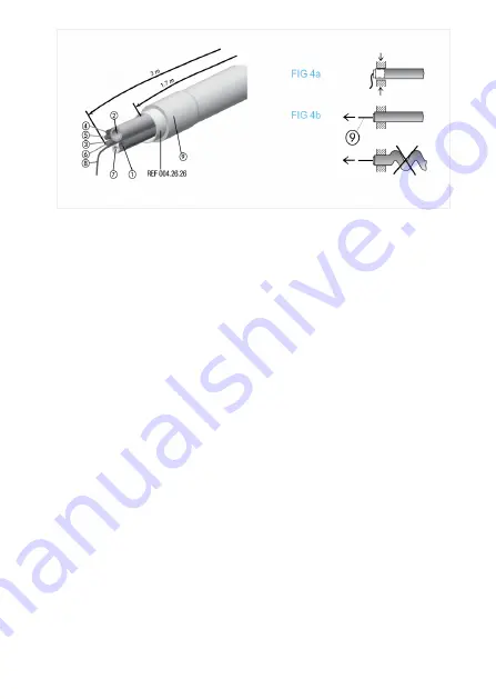
4.3 Assembly
Preserve the initial alignment of the wires and tubes. Place the metal re-
inforcement ring (9) in the chucking zone (
).
The securing cord (8) must be attached to the chassis of the unit or table-top
device to avoid any traction on the wires and tubes (
).
The outer tube must not be wrinkled after installation. The resistance to traction is
60N maximum.
Description
1. Ø 1.5/2.5 mm green: waterspray
2. Ø 1.5/2.5 mm white: airspray
3. (+) red: motor
4. (0V) black: motor
5. (+) brown: bulb
6. (0V) blue: bulb
7. Ø 2.8/4.1 mm white: cooling MC3
8. Red: return air
9. Securing cord
10. Sheath silicone
10
FIG. 4


